


MII PHY Registers
2-16
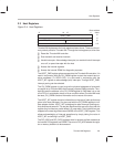
The status register (GEN_sts in ThunderLAN products) includes bits to identify
the technology supported by the PHY. This technology includes protocol and
duplex abilities. It indicates link, jabber, and autoconfiguration completion. Bit
0 of the status register also indicates whether the extended register set is sup-
ported.
The PHY identifier registers (GEN_id_hi/GEN_id_lo in ThunderLAN products)
contain an identifier code for the silicon revision and the silicon manufacturer.
Registers 0x04 thru 0x07 are used in the autonegotiation process. They in-
clude the autonegotiation advertisement, autonegotiation link partner ability,
autonegotiation expansion, and autonegotiation next page registers (AN_adv,
AN_lpa, AN_exp respectively).
In the vendor-specific area, Texas Instruments has implemented a TLPHY_id
register. This register is used to identify ThunderLAN-specific PHY devices.
ThunderLAN also implements a specific control register, TLPHY_ctl, and sta-
tus register, TLPHY_sts. The particulars of these registers change from PHY
to PHY. Please refer to Appendix A for the PHY that you are using.
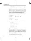
Writing to a register in a PHY through the management interface involves writ-
ing data and clock bits into NetSio
,
an internal register, which uses the pointer
host registers. The data unit to or from a PHY register is always 16 bits.
The NetSio register uses three bits to drive the MDIO/MDCLK MII manage-
ment interface. These bits are MCLK, MTXEN, and MDATA. These bits directly
control the voltages present in the management interface and function like
this:
MCLK directly controls the MDCLK signal. Setting MCLK in NetSio high
causes a logic 1 to appear on the MDCLK pin. Setting MCLK in the NetSio
register low causes a logic 0 to appear on the MDCLK pin.
MTXEN controls the direction of the MDIO pin.
When MTXEN is high, MDIO is driven with the value written on
MDATA.
When MTXEN is low, MDATA mirrors the MDIO line.
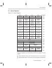
Multiple PHYs can be attached to one MII. PHYs are selected through an ad-
dress which can be in a range from 0x00 to 0x1F. Some vendors’ PHYs have
pins that can be pulled up or down to indicate the PHY address. In order for
a particular PHY to be addressed, the driver must know the PHY address be-
forehand.
ThunderLAN’s internal PHY for 10Base-T can only support two addresses.
When used in conjunction with the rest of the ThunderLAN device, the address