


4 Replacement Procedures 4.17 DC-IN cable, RGB Board and RJ45 cable
4.17 DC-IN cable, RGB Board and RJ45 cable
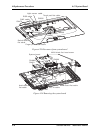
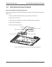
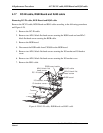
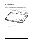
Removing DC-IN cable, RGB Board and RJ45 cable
Remove the DC-IN cable, RGB Board and RJ45 cable according to the following procedures
and Figure 4-28.
1. Remove the DC-IN cable.
2. Remove two M2x3 black flat head screws securing the RGB board and one M2x3
black flat head screw securing the RGB cable.
3. Remove the RGB board.
4. Disconnect the RGB cable from CN9600 on the RGB board.
5. Remove two M2x3 black flat head screws securing the IO bracket and IO bracket
cover.
6. Remove two M2x3 black flat head screws securing the IO bracket cover.
7. Remove the RJ45 cable.
M2x3 black flat
head screw
M2x3 black flat
head screw
RJ45 cable
RGB board
RGB board cable
DC IN cable-
IO bracket
IO bracket cover
Figure 4-28 DC-IN cable, RGB Board and RJ45 cable
4-46 Satellite/E200/E205 Maintenance
Manual