


B070/B071 9-4 PTM
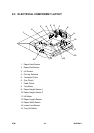
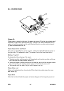
9.3.1 ELECTRICAL COMPONENT DESCRIPTIONS
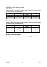
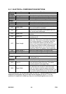
Symbol Name Function
Clutches
MC8 Transport Drives the transport rollers in the bypass tray.
MC9 Paper Feed Drives the paper feed roller in the bypass tray.
MC10 Grip Drives the grip clutch in the bypass tray.
Motors
M5 Tray Drives all rollers in the bypass tray.
M6 Tray Lift Lifts and lowers the tray.
Sensors
S23 Paper Feed
Detects the copy paper coming to the paper feed
roller and checks for misfeeds.
S24 Lift
Detects when the paper in the bypass tray is at
the correct paper feed height.
S25 Lower Limit
Detects when the tray is at its lowest possible
position.
S26 Paper End
Informs the copier when the paper in the bypass
tray has run out.
S27 Paper Length
Used with the paper width switch to determine
paper size. This sensor is activated when paper is
set for short edge feed. For example, when the
paper width switch detects A4 width and this
sensor is off, the machine determines A4 is set for
long edge feed. When A4 width is detected and
the paper length sensor is on, then the machine
determines that A3 is loaded for short edge feed.
S28 Paper Height 1 Detects the paper height in the bypass tray.
S29 Paper Height 2 Detects the paper height in the bypass tray.
Solenoid
s
SOL7 Pick-up
Controls up-down movement of the pick-up roller
in the bypass tray.
Switches
SW5 Tray Lift
Switches the tray lift motor on and off to lift and
lower the bottom plate of the tray. This switch
must be pressed to start paper feed.
SW6 Paper Width
A slide switch connected to the side fences. When
the side fences are moved to match the paper
width, four feelers inside the paper size switch
slide along wiring patterns of a terminal plate. The
wire pattern detected determines the paper width.
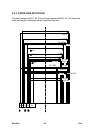
The numbering for the components does not start at 1 because the point-to-point
diagram for the bypass tray is included on the diagram for the LCT. For the
purpose of component numbering, they are considered together as one unit.