


PTM 2-12 B070/B071
2.2 SCANNING
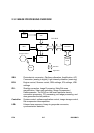
2.2.1 OVERVIEW
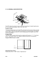
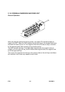
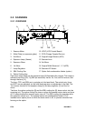
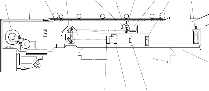
1. Scanner Motor 10. LCDC (LCD Control Board)
2. White Plate (on exposure glass) 11. CCD (Charge Coupled Device)
3. 2nd Mirror 12. Original Length Sensor (APS)
4. Exposure Lamp (Xenon) 13. Scanner Lens
5. Exposure Glass 14. 3rd Mirror
6. 1st Mirror 15. Original Width Sensors 1, 2, 3 (APS)
7. Lamp Regulator 16. Scanner HP Sensor
8. SBU Cooling Fan 17. Optics Anti-condensation Heater (option)
9. Optics Cooling Fan
One xenon lamp (23W) as the exposure lamp [4] illuminates the original. The image is
reflected onto the CCD [11] (600 dpi resolution) via the 1st, 2nd, and 3rd mirrors, and
through the lens [13].
The lens, CCD, and SBU are in a single unit, the lens block. The optical axis, focus,
and MTF are pre-adjusted, so this lens block requires no adjustment in the field. The
1st scanner consists of the exposure lamp [4], the lamp regulator [7] and the 1st
mirror.
Two fans, the optics cooling fan [9] and the SBU cooling fan [8], draw cool air into the
scanning unit. The optics cooling fan turns on when the scanner motor starts and turns
off 10 seconds after the scanner motor turns off. The SBU cooling fan operates while
the operation switch is on. The optional optics anti-condensation heater [17] (if
installed as an option) turns on while the main switch is off, to prevent moisture from
forming on the optics.
B070D001.WMF
10
11
12
13
1
2
3
4
5
6
7
8
9