


1 Hardware Overview
1-iv [CONFIDENTIAL] Satellite R20/TECRA M7 Maintenance Manual (960-572)
Figures
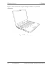
Figure 1-1 Front of the computer..................................................................................... 1-6
Figure 1-2 System units configuration ............................................................................ 1-7
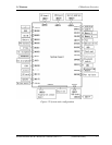
Figure 1-3 System block diagram.................................................................................... 1-8
Figure 1-4 2.5-inch HDD............................................................................................... 1-14
Figure 1-5 DVD-ROM drive ......................................................................................... 1-17
Figure 1-6 DVD-ROM & CD-R/RW drive................................................................... 1-19
Figure 1-7 DVD Super Multi drive ............................................................................... 1-22
Figure 1-8 Keyboard...................................................................................................... 1-25
Figure 1-9 LCD module................................................................................................. 1-26
Tables
Table 1-1 2.5-inch HDD Specifications....................................................................... 1-14
Table 1-2 DVD-ROM drive outline dimensions.......................................................... 1-17
Table 1-3 DVD-ROM drive specifications .................................................................. 1-18
Table 1-4 DVD-ROM & CD-R/RW drive outline dimensions.................................... 1-19
Table 1-5 DVD-ROM & CD-R/RW drive specifications............................................ 1-20
Table 1-6 DVD Super Multi drive outline dimensions................................................ 1-22
Table 1-7 DVD Super Multi drive specifications ........................................................ 1-23
Table 1-8 LCD module specifications (14.1 TFT)....................................................... 1-26
Table 1-9 FL inverter board specifications .................................................................. 1-27
Table 1-10 Power supply output specifications ............................................................. 1-29
Table 1-11 Battery specifications................................................................................... 1-31
Table 1-12 Time required for charges of main battery .................................................. 1-32
Table 1-13 Data preservation time ................................................................................. 1-32
Table 1-14 RTC battery charging/data preservation time.............................................. 1-33
Table 1-15 AC adapter specifications ............................................................................ 1-34