


2.1 Troubleshooting 2 Troubleshooting
2
2.1 Troubleshooting
Chapter 2 describes how to determine which Field Replaceable Unit (FRU) in the computer is
causing the computer to malfunction. (The “FRU” means the replaceable unit in the field.)
The FRUs covered are:
1. Power supply 9. Modem
2. System board 10. Bluetooth
3. 3.5” USB FDD 11. LAN
4. 2.5” HDD 12. Sound
5. Keyboard 13. Bridge media slot
6. Display 14. Tablet pen
7. Touch pad 15. Wireless LAN
8. Optical drive 16. Fingerprint sensor
The Detailed replacement procedures are given in Chapter 4. Test Program operations are
described in Chapter 3.
NOTE: After replacing the System board or CPU, it is necessary to execute the subtest 01
Initial configuration of 3.3 Setting of the hardware configuration in Chapter 3.
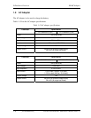
The following tools are necessary in addition to tools described in Chapter 3 for implementing
the Diagnostics procedures:
1. Phillips screwdrivers
2. Toshiba DOS system FD
3. Debug test cable (for debug port test)
4. RS-232C cross-cable (for debug port test)
5. Test board (for debug port test)
6. External monitor (for display check)
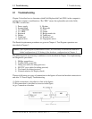
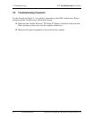
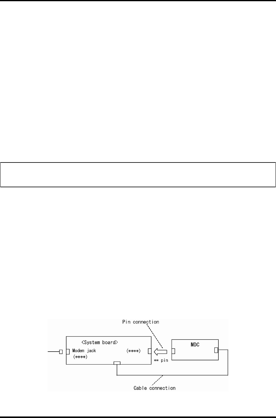
There are following two types of connections in the figures of board and module connection in
and after 2.3 Power Supply Troubleshooting.
(1) Cable connection is described as a line in the figures.
(2) Pin connection is described as an arrow in the figure.
<e.g> Connection of modem
Satellite R20/TECRA M7 Maintenance Manual (960-572) [CONFIDENTIAL] 2-1