4. Slide the grommet up the cord and push its narrow end into the modular
jack. When properly installed, the grommet should fit flat against the rear
of the PINpad device.
Cable Part Numbers
Part No. Description
10441-01 0.6 M, coiled (stretches
to 7 ft.)
10441-02 1.1 M, coiled (stretches to 15 ft.)
01582-00 1 M, straight
01582-01 3.6 M, straight
01582-02 7.6 M, straight
PINpad 101 Device Mounting
The optional PINpad mount holds
your PINpad unit securely to a
counter top or a wall. The PINpad
device can be lifted from the
mount anytime for hand-held
operation.
First select a location for the
mount on a smooth wall or
countertop. Be sure the cable can
easily reach the terminal from this
position without stretching.
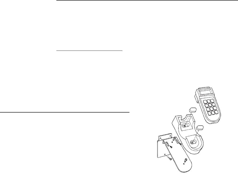
Wall Mounting 1. Screw the flat wall plate securely to the wall as shown in Figure B-4. Use
screw anchors if you are fastening the mount to a cement or brick wall. If
you are fastening the plate to drywall, the screws must go into the studs
behind the wall. Screw anchors alone will not safely hold the PINpad
mount to drywall.
2. Fasten the angled metal bracket to the wall mount using the TORX
machine screws provided. The two slots on the bracket allow a TORX
screwdriver to reach these screws.
3. Insert the two large slotted screws into the top of the angled bracket but do
not tighten them yet.
4. Position the keyholes on the molded cradle over the slotted screws on the
angled bracket. Slide the mount to the right until both screws are in the
narrow ends of the keyholes. If necessary, loosen the screws slightly
until the cradle slides easily.
5. Tighten the slotted screws to secure the cradle to the angled bracket.
Insert the small molded covers to conceal the keyholes.
6. Place the PINpad device firmly into cradle.
Figure B-4. PINpad Unit Mount
Components (Exploded View)
FDC Retail/Debit Purchasing Card Reference Manual
B - 4 TRANZ 460 Terminal


