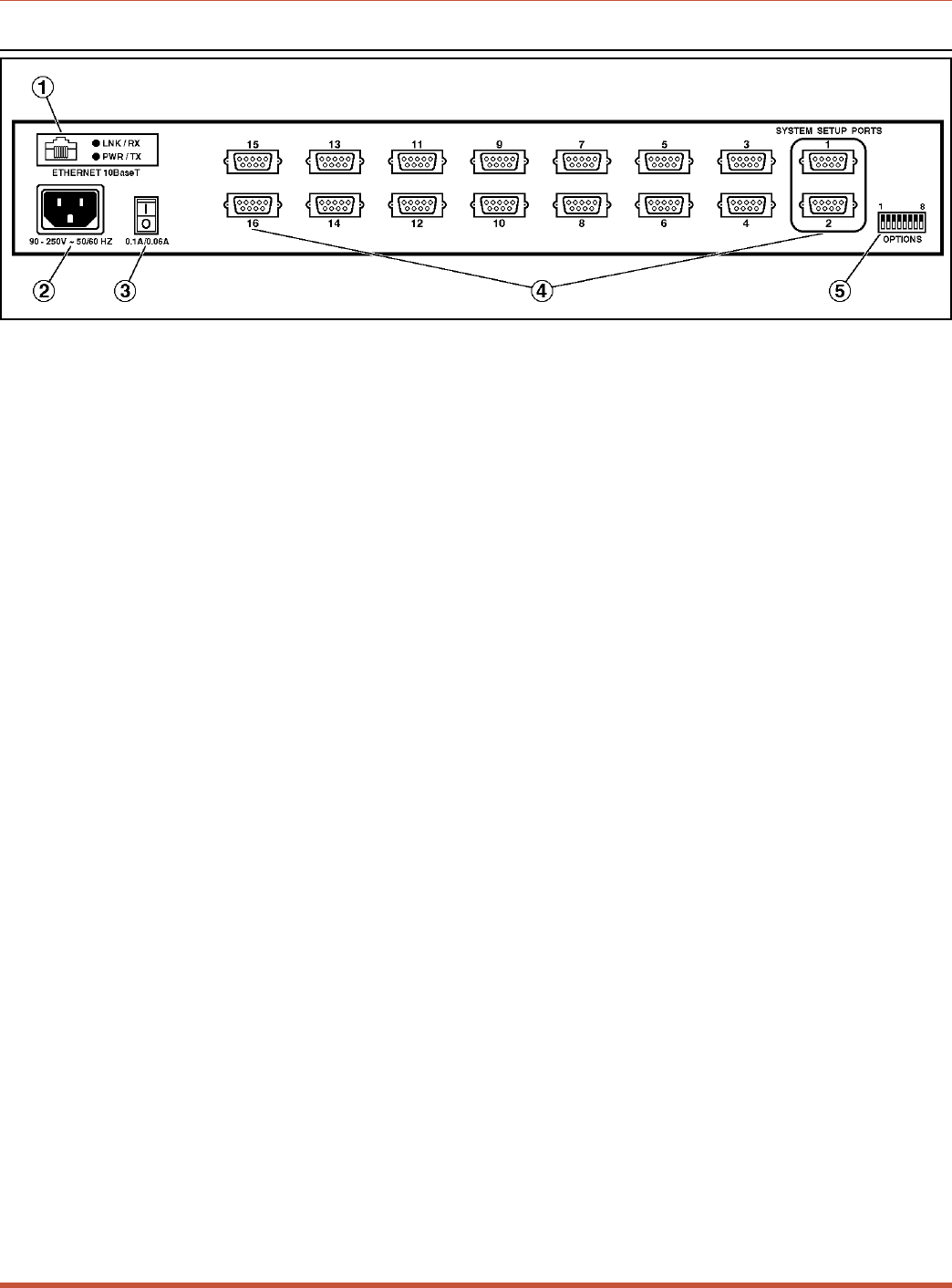
2.2. Back Panel
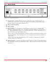
À
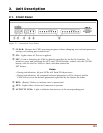
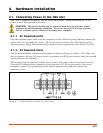
Network Port: An RJ45 Ethernet port for connection to your TCP/IP network. To
communicate via network, you must first specify the IP Address, Subnet Mask, and
Gateway Address as described in Section 5.5.4.
Á
Power Cable Receptacle
Â
Power Switch
Ã
RS232 PORTS: For connection to console ports on target devices. Standard DB9
connectors configured as DTE ports. The RS232 ports are similar to a serial port on a
PC. When connecting a modem, use a standard serial cable. When connecting a PC or
other DTE device use a null modem cable.
• Ports 1 and 2 are System Setup Ports, which are used for communication during set-up
and configuration. Note that Supervisor Level command access cannot be disabled at
these ports.
• Ports 1 and 2 can either be connected to a PC or modem. Connection to a modem
allows control by a remote PC.
Ä
Option Switches: A bank of eight DIP switches, which are used to set the default baud
rate, handshake, message type, and duplex mode. Option Switch functions are described
in Section 4.2.
2-2
CMS Series - Console Management Switches, User's Guide Unit Description
Figure 2.2: Instrument Back Panel


