Calibration (6000 Watt only)
B–14 TM-XDOP-01XN
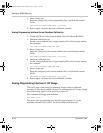
5. Enter voltage data
Enter the voltage at the current programming lines, read from the external
DVM.
CAL:ANAL:5V:PROG:CURR:DATA <voltage>
6. Power supply calculates and stores calibration constants.
Analog Programming Interface Current Readback Calibration
1. Attach a DVM across the current readback lines, Pins B6 and B1(GND).
2. Minimum calibration level
Set the current readback lines to approximately 10% of full scale by sending
the command:
CAL:ANAL:5V:READ:CURR:LEV MIN
3. Enter voltage data
Enter the voltage across the current readback lines, read from the external
DVM.
CAL:ANAL:5V:READ:CURR:DATA <voltage>
4. Maximum calibration level
Set the current readback lines to approximately 90% of full scale by sending
the command:
CAL:ANAL:5V:READ:CURR:LEV MAX
5. Enter voltage data
Enter the voltage across the current readback lines, read from the external
DVM.
CAL:ANAL:5V:READ:CURR:DATA <voltage>
6. Power supply calculates and stores calibration constants.
Analog Programming Interface 0-10V Range
The 0-10V range of the analog programming interface must be calibrated
separately. Follow the procedure exactly as for calibrating the 0-5V range, except
that all the analog signals will be scaled by a factor of 2.
The commands will begin with the header:
CAL:ANAL:10V:...
The inputs to the programming lines should be approximately 1V for the
minimum calibration level and 9V for the maximum calibration level.
TM-XDOP-01XN.book Page 14 Monday, July 17, 2006 11:19 AM


