


PREINSTALLATION
of the equipment. For example, having paper as close to the
printer as possible will save time.
• Having the system controller as close as possible to any
offline interface devices saves time when monitoring tapes,
jobs, and so forth.
Delivery access requirements
It is easy to overlook how the equipment is going to get from
the truck to the operation site. Does it need to go up stairs?
Do you have an elevator if it is to be located above the first
floor? Is the elevator large enough? How wide are the hallways?
The doorways? Do you have a loading dock or a specific door to
which the equipment should be delivered?
All these issues need to be reviewed prior to or at the time of
the site inspection that is done by your service representative.
The equipment dimensions are specified earlier in this chapter,
so it is easy to know whether or not your hallways and doorways
are wide enough to permit travel through them.
Turning radius The width of the passageway when the equipment must
negotiate a corner, whether into a room (or elevator) or into
another passageway, must also be considered.
The 4635 is delivered with the printer, inverter feeder/stacker,
and the feeder/stacker as three separate modules. If necessary,
the printer can be separated into two pieces for easier moving.
The larger of the two parts contains the xerographic system; the
smaller of the parts (referred to here as the PHM) contains paper
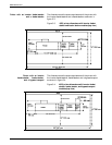
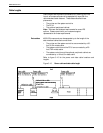
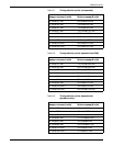
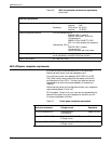
trays 1 and 2. Table 3-1 describes the turning requirements for
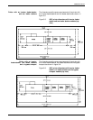
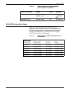
the printer when attached to the PHM (not separated). Table 3-2
describes requirements for the printer without the PHM
(separated). Do not confuse these two parts of the printer with
the inverter and feeder/stacker modules, which have their own
turning requirements.
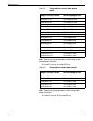
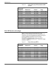
Table 3-3 describes the turning requirements for the printer if it is
upended for easier moving or stair-climbing. This table reflects
requirements for the printer separated from the PHM.
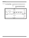
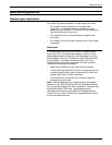
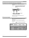
Tables 3-4 and 3-5 describe the turning requirements for the
inverter/feeder/stacker and the feeder/stacker modules.
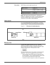
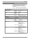
The relatively small dimensions of the 4635 system controller and
the optional peripheral cabinet are not likely to be of concern
during delivery. Refer to figures 3-1 and 3-2 for their dimensions.
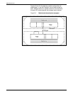
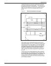
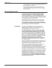
The diagrams and the tables that follow show the minimum space
needed to maneuver through a turn. To use the tables, measure
the passage or doorway width into which you wish to go at its
minimum width. This is Passage A. Find that number (or the
next higher number) on the appropriate table and read across to
the corresponding minimum value for Passage B (the passage or
doorway you are turning from).
3-12 XEROX 4635 LASER PRINTING SYSTEM INSTALLATION PLANNING GUIDE