


PREINSTALLATION
50 Hz system controller and peripheral cabinet power cord configurations
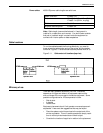
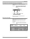
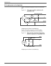
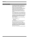
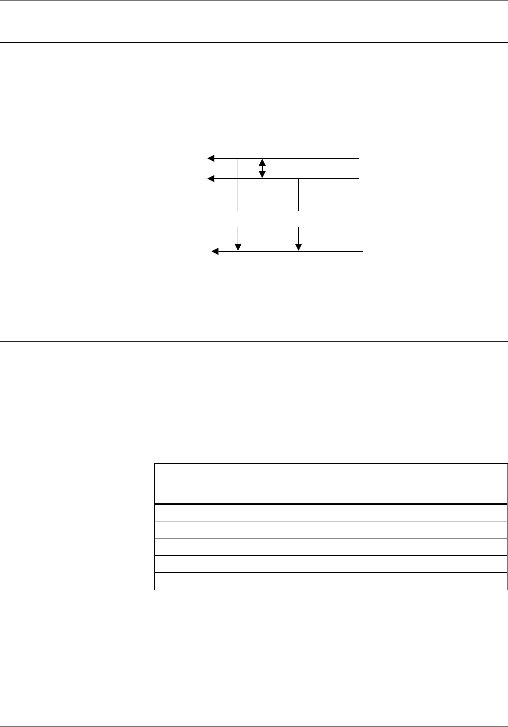
Figure 3-12 shows the 50 Hz system controller power cord
configuration.
Figure 3-12. System controller and peripheral cabinet power
cord 50 Hz installation 200/230 VAC, single
phase, 15A
NEUTRAL
BLUE
BROWN
LINE
0 VAC 200/2300 VAC
GREEN/YELLOW TRACER
GROUND
200/2300 VAC
Note that 50 Hz plug and receptacle specifications vary
according to local codes.
60 Hz printer outlet voltages
Note: All power outlets must have a dedicated circuit for each
system equipment piece. Ensure that each power cord has a
separate circuit.
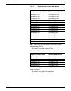
Refer to table 3-12 for the 60Hz voltage requirements at the
power outlet.
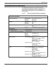
Table 3-12. Printer (50 Hz) voltage requirements at power
outlet
Service outlet
configuration Measurement Nominal Range
4 Wire Line 1 to Neutral 120 V RMS 107-127 V RMS
4 Wire Line 2 to Neutral 120 V RMS 107-127 V RMS
4 Wire Neutral to Ground 0 0-10 V RMS
4 Wire Line 1 to Line 2 208 V RMS 182-220 V RMS
4 Wire Line 1 to Line 2 240 V RMS 210-254 V RMS
XEROX 4635 LASER PRINTING SYSTEM INSTALLATION PLANNING GUIDE 3-19