


PREINSTALLATION
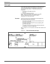
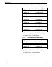
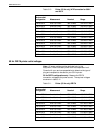
Table 3-10. Printer (50 Hz only) WYE connection for 380 V
and 400 V
Service outlet
configuration Measurement Nominal Range
5 Wire 380 V Line 1 to Line 2 380 V RMS 342-419 V RMS
5 Wire 380 V Line 2 to Line 3 380 V RMS 342-419 V RMS
5 Wire 380 V Line 1 to Line 3 380 V RMS 342-419 V RMS
5 Wire 380 V Line 1 to Neutral 220 V RMS 198-242 V RMS
5 Wire 380 V Line 2 to Neutral 220 V RMS 198-242 V RMS
5 Wire 380 V Line 3 to Neutral 220 V RMS 198-242 V RMS
5 Wire 400 V Line 1 to Line 2 400 V RMS 358-438 V RMS
5 Wire 400 V Line 2 to Line 3 400 V RMS 358-438 V RMS
5 Wire 400 V Line 1 to Line 3 400 V RMS 358-438 V RMS
5 Wire 400 V Line 1 to Neutral 230 V RMS 207-253 V RMS
5 Wire 400 V Line 2 to Neutral 230 V RMS 207-253 V RMS
5 Wire 400 V Line 3 to Neutral 230 V RMS 207-253 V RMS
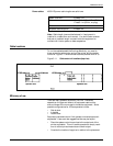
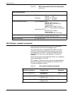
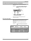
50 Hz DELTA printer outlet voltages
Note: All power outlets must be dedicated only to this
equipment. Ensure that each power cord has a separate circuit.
Consult with your service representative to determine the type of
plug and receptacle to be used for your 50 Hz printer.
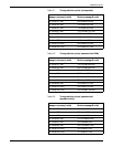
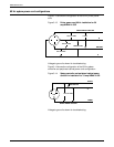
50 Hz DELTA configurations only: Measure the DELTA
connection voltages at the power source. The required voltages
are shown in table 3-11.
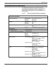
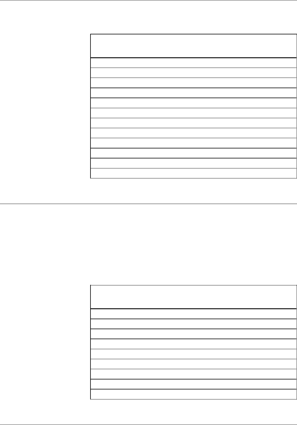
Table 3-11. Printer (50 Hz only) DELTA
Service outlet
configuration Measurement Nominal Range
4 Wire 220V V Line 1 to Line 2 220 V RMS 198-242 V RMS
4 Wire 220V V Line 2 to Line 3 220 V RMS 198-242 V RMS
4 Wire 220V V Line 1 to Line 3 220 V RMS 198-242 V RMS
4 Wire 230 V Line 1 to Line 2 230 V RMS 207-253 V RMS
4 Wire 230 V Line 2 to Line 3 230 V RMS 207-253 V RMS
4 Wire 230 V Line 1 to Line 3 230 V RMS 207-253 V RMS
4 Wire 240 V Line 1 to Line 2 240 V RMS 216-264 V RMS
4 Wire 240 V Line 2 to Line 3 240 V RMS 216-264 V RMS
4 Wire 240 V Line 1 to Line 3 240 V RMS 216-264 V RMS
3-18 XEROX 4635 LASER PRINTING SYSTEM INSTALLATION PLANNING GUIDE