


Specifications
Paper Specification
114
P1003636-002 TTP 7030™ Technical Manual 10/05/2009
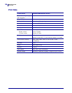
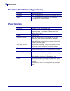
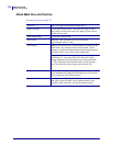
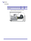
Black Mark Size and Position
See also Page Setup on page 85.
Print side Inner side (opposite to thermal coating side)
Sensor position 25 mm before cutter, and 9.1 mm from left edge of ticket
entry when seen from the front of the printer (on the side of
the blue release arm).
Mark length range 3 to 18 mm, default 5 mm
Mark width Minimum 5 mm centered on the sensor position,
recommended width is 9 mm
Print density Standard wet offset mode is recommended for printing of the
black-marks. The full mark area must be printed. Screen-
printing is not allowed. Measurement of print density must be
performed relative to the white paper background.
Using a MacBeth densitometer, the print density must be
greater than 1.3. Anti-gloss filter is not allowed. Using a
Gretag densitometer, the print density must be greater than
1.5. The reflection from the black-mark must be less than
10%. The reflection from the paper must exceed 80%.
Preprinting Preprinting in the zone passing over the black-mark sensor is
not recommended. If required, OCR blind type of ink must be
used, (outside the 700-1100 nm range).
Punched holes
Punching must be done from the thermally coated side. Distorted
print can be expected within a zone of approximately 2-mm
around the edges of the hole. The function must be tested.