


4929-A2-ZN20-30 4929 DSLAM Installation and User’s Guide 83
CONNECTORS AND PIN ASSIGNMENTS
Overview
The following sections provide pin assignments for:
z DSL Ports and POTS Splitter Connectors on page 83
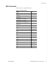
z SFP Connector on page 85
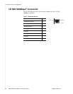
z 10/100/1000BaseT Connector on page 86
z DB9 to RJ45 Adapter Pinouts on page 87
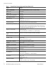
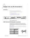
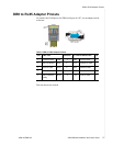
Figure 2: 4929 DSLAM Front Panel
DSL Ports and POTS Splitter Connectors
The 50-pin RJ21X Telco connector labeled DSL Ports 1–24 provides the
2-wire loop interface from each DSL port to the demarcation point. (The
Canadian designation for this connector is CA21A.) The 50-pin RJ21X Telco
connector labeled POTS 1–24 provides the interface with the internal POTS
splitters, if installed.
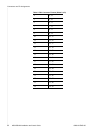
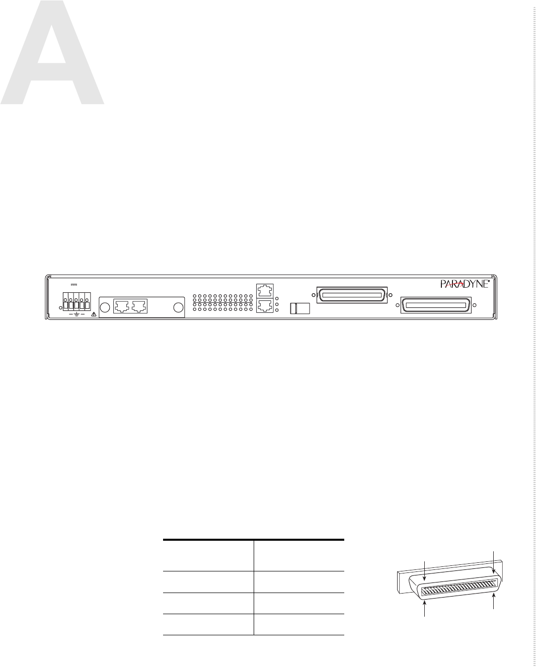
Table 5 lists the pin assignments for each of these interfaces. Note that Pins 25
and 50 are not used.
POTS
ADSL2+
05-17614
PWR
48 1.24A
MAX
1 2 3 4 5 6 7 8 9
13 14 15 16 17 18 19 20 21 22 23 24
10 11 12
COM
Lnk
Act
Dup
10/10/1000
SFP
MIM2 T1/E1
MIM
+
ACT
4929
+
LK
ACT
LK
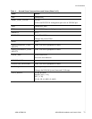
Table 5: DSL Connector Pinouts (Sheet 1 of 2)
DSL Port
Connector Pins
(Ring, Tip)
11, 26
22, 27
33, 28
25
02-17151
1
50
26