


Chapter 11 Spanning Tree Protocol
ES-2024 Series User’s Guide
104
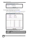
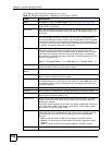
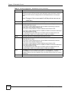
The following table describes the labels in this screen.
Table 25 Advanced Application > Spanning Tree Protocol > MSTP
LABEL DESCRIPTION
Status Click Status to display the MSTP Status screen (see Figure 48 on page 106).
Active Select this check box to activate MSTP on the Switch. Clear this check box to
disable MSTP on the Switch.
Hello Time This is the time interval in seconds between BPDU (Bridge Protocol Data Units)
configuration message generations by the root switch. The allowed range is 1 to
10 seconds.
MAX Age This is the maximum time (in seconds) a switch can wait without receiving a BPDU
before attempting to reconfigure. All switch ports (except for designated ports)
should receive BPDUs at regular intervals. Any port that ages out STP information
(provided in the last BPDU) becomes the designated port for the attached LAN. If it
is a root port, a new root port is selected from among the Switch ports attached to
the network. The allowed range is 6 to 40 seconds.
Forwarding Delay This is the maximum time (in seconds) a switch will wait before changing states.
This delay is required because every switch must receive information about
topology changes before it starts to forward frames. In addition, each port needs
time to listen for conflicting information that would make it return to a blocking
state; otherwise, temporary data loops might result. The allowed range is 4 to 30
seconds. As a general rule:
Note: 2 * (Forward Delay - 1) >= Max Age >= 2 * (Hello Time + 1)
Maximum hops Enter the number of hops (between 1 and 255) in an MSTP region before the
BPDU is discarded and the port information is aged.
Configuration
Name
Enter a descriptive name (up to 32 characters) of an MST region.
Revision Number Enter a number to identify a region’s configuration. Devices must have the same
revision number to belong to the same region.
Apply Click Apply to save your changes to the Switch’s run-time memory. The Switch
loses these changes if it is turned off or loses power, so use the Save link on the
top navigation panel to save your changes to the non-volatile memory when you
are done configuring.
Cancel Click Cancel to begin configuring this screen afresh.
Instance Use this section to configure MSTI (Multiple Spanning Tree Instance) settings.
Instance Enter the number you want to use to identify this MST instance on the Switch. The
Switch supports instance numbers 0-16.
Bridge Priority Set the priority of the Switch for the specific spanning tree instance. The lower the
number, the more likely the Switch will be chosen as the root bridge within the
spanning tree instance.
Enter priority values between 0 and 61440 in increments of 4096 (thus valid values
are 0, 4096, 8192, 12288, 16384, 20480, 24576, 28672, 32768, 36864, 40960,
45056, 49152, 53248, 57344 and 61440).
VLAN Range Enter the start of the VLAN ID range that you want to add or remove from the
VLAN range edit area in the Start field. Enter the end of the VLAN ID range that
you want to add or remove from the VLAN range edit area in the End field.
Next click:
• Add - to add this range of VLAN(s) to be mapped to the MST instance.
• Remove - to remove this range of VLAN(s) from being mapped to the MST
instance.
• Clear - to remove all VLAN(s) from being mapped to this MST instance.
Enabled VLAN(s) This field displays which VLAN(s) are mapped to this MST instance.