


Chapter 11 Spanning Tree Protocol
ES-2024 Series User’s Guide
97
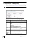
11.1.3 STP Port States
STP assigns five port states to eliminate packet looping. A bridge port is not allowed to go
directly from blocking state to forwarding state so as to eliminate transient loops.
11.1.4 Multiple STP
Multiple Spanning Tree Protocol (IEEE 802.1s) is backward compatible with STP/RSTP and
addresses the limitations of existing spanning tree protocols (STP and RSTP) in networks to
include the following features:
• One Common and Internal Spanning Tree (CIST) that represents the entire network’s
connectivity.
• Grouping of multiple bridges (or switching devices) into regions that appear as one single
bridge on the network.
• A VLAN can be mapped to a specific Multiple Spanning Tree Instance (MSTI). MSTI
allows multiple VLANs to use the same spanning tree.
• Load-balancing is possible as traffic from different VLANs can use distinct paths in a
region.
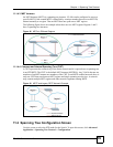
11.1.4.1 MSTP Network Example
The following figure shows a network example where two VLANs are configured on the two
switches. If the switches are using STP or RSTP, the link for VLAN 2 will be blocked as STP
and RSTP allow only one link in the network and block the redundant link.
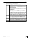
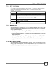
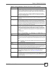
Table 22 STP Port States
PORT STATE DESCRIPTION
Disabled STP is disabled (default).
Blocking Only configuration and management BPDUs are received and processed.
Listening All BPDUs are received and processed.
Note: The listening state does not exist in RSTP.
Learning All BPDUs are received and processed. Information frames are submitted to the
learning process but not forwarded.
Forwarding All BPDUs are received and processed. All information frames are received and
forwarded.