


Chapter 3 Hardware Overview
ES-2024 Series User’s Guide
40
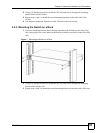
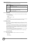
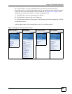
Figure 12 Opening the Transceiver’s Latch Example
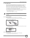
2 Pull the transceiver out of the slot.
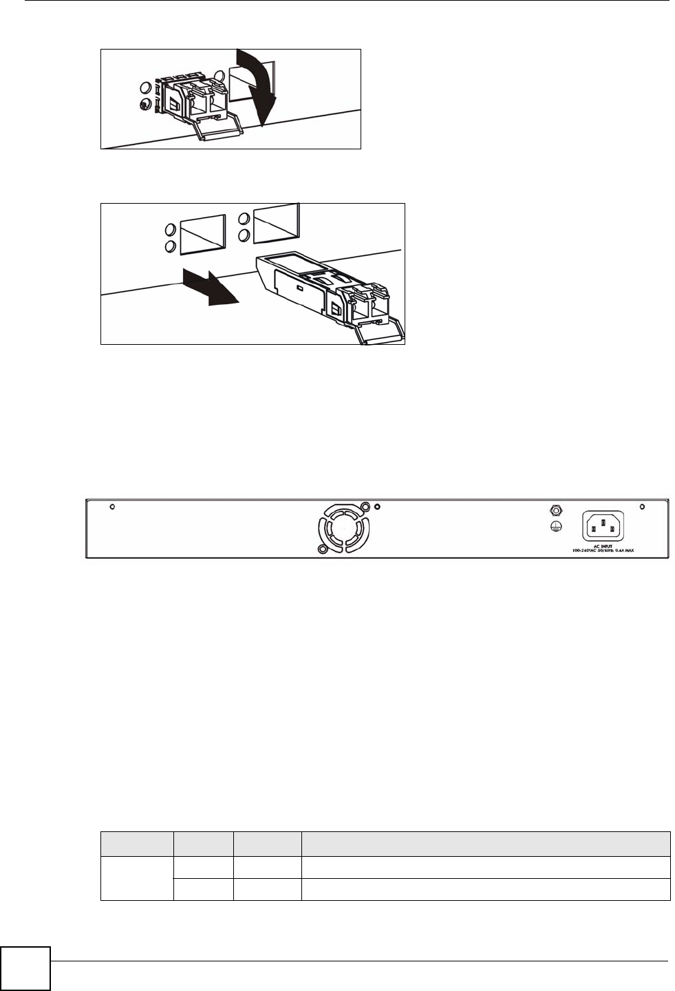
Figure 13 Transceiver Removal Example
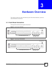
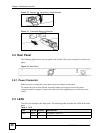
3.2 Rear Panel
The following figure shows the rear panel of the Switch. The power receptacle is on the read
panel.
Figure 14 Rear Panel
3.2.1 Power Connector
Make sure you are using the correct power source as shown on the panel.
To connect the power to the Switch, insert the female end of power cord to the power
receptacle on the rear panel. Connect the other end of the supplied power cord to the power
source.
3.3 LEDs
The LEDs are located on the front panel. The following table describes the LEDs on the front
panel.
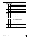
Table 2 LEDs
LED COLOR STATUS DESCRIPTION
PWR Green On The system is turned on.
Off The system is off.