


Chapter 7 Basic Setting
ES-2024 Series User’s Guide
71
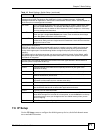
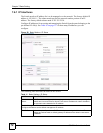
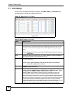
7.6 IP Setup
Use the IP Setup screen to configure the default gateway device, the default domain name
server and add IP domains.
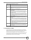
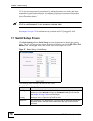
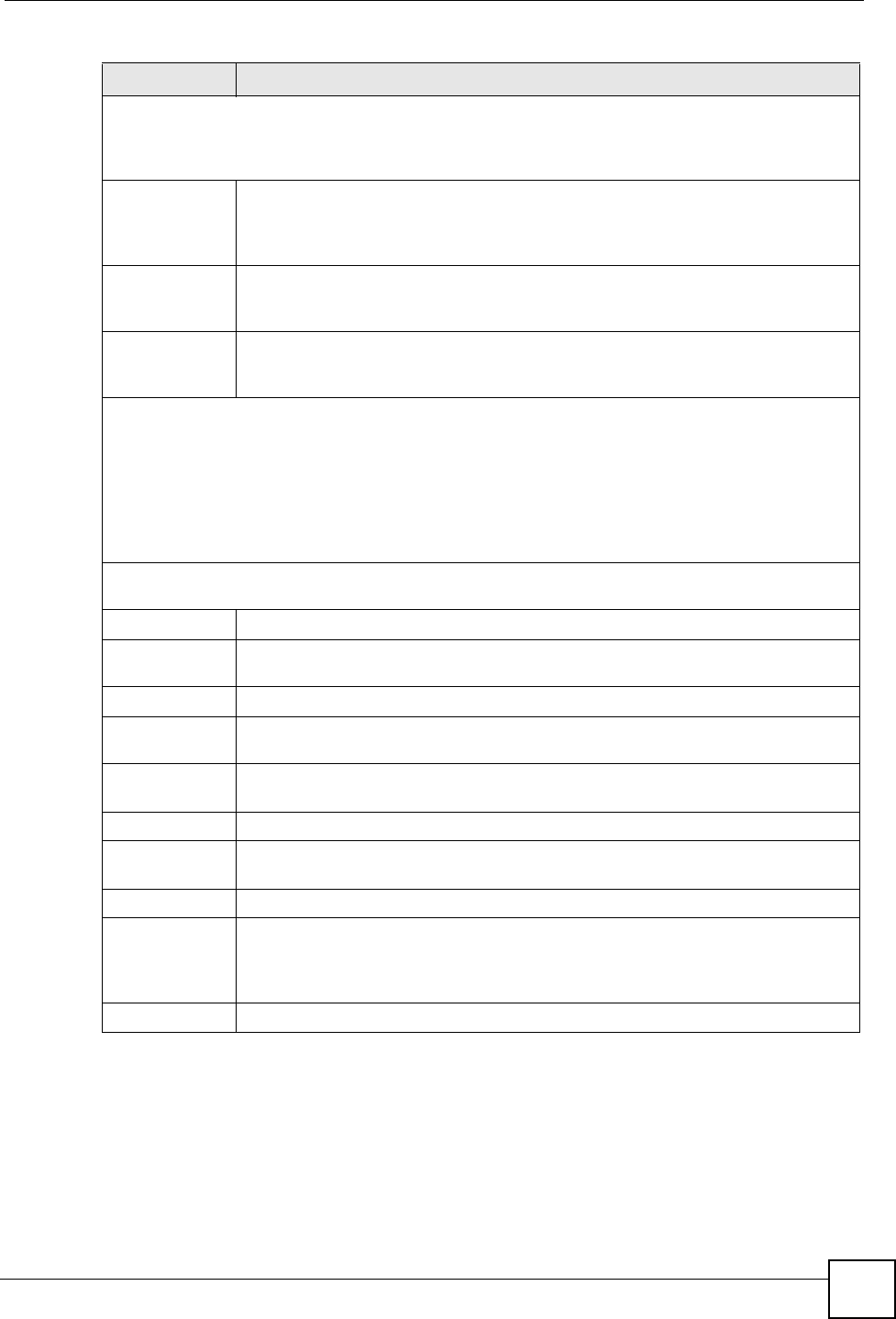
GARP Timer: Switches join VLANs by making a declaration. A declaration is made by issuing a Join
message using GARP. Declarations are withdrawn by issuing a Leave message. A Leave All
message terminates all registrations. GARP timers set declaration timeout values. See the chapter on
VLAN setup for more background information.
Join Timer Join Timer sets the duration of the Join Period timer for GVRP in milliseconds. Each
port has a Join Period timer. The allowed Join Time range is between 100 and
65535 milliseconds; the default is 200 milliseconds. See the chapter on VLAN setup
for more background information.
Leave Timer Leave Time sets the duration of the Leave Period timer for GVRP in milliseconds.
Each port has a single Leave Period timer. Leave Time must be two times larger
than Join Timer; the default is 600 milliseconds.
Leave All Timer Leave All Timer sets the duration of the Leave All Period timer for GVRP in
milliseconds. Each port has a single Leave All Period timer. Leave All Timer must be
larger than Leave Timer.
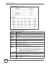
Priority Queue Assignment
IEEE 802.1p defines up to eight separate traffic types by inserting a tag into a MAC-layer frame that
contains bits to define class of service. Frames without an explicit priority tag are given the default
priority of the ingress port. Use the following fields to configure the priority level-to-physical queue
mapping.
The Switch has four physical queues that you can map to the 8 priority levels. On the Switch, traffic
assigned to higher index queues gets through faster while traffic in lower index queues is dropped if
the network is congested.
Priority Level (The following descriptions are based on the traffic types defined in the IEEE 802.1d
standard (which incorporates the 802.1p).
Level 7 Typically used for network control traffic such as router configuration messages.
Level 6 Typically used for voice traffic that is especially sensitive to jitter (jitter is the
variations in delay).
Level 5 Typically used for video that consumes high bandwidth and is sensitive to jitter.
Level 4 Typically used for controlled load, latency-sensitive traffic such as SNA (Systems
Network Architecture) transactions.
Level 3 Typically used for “excellent effort” or better than best effort and would include
important business traffic that can tolerate some delay.
Level 2 This is for “spare bandwidth”.
Level 1 This is typically used for non-critical “background” traffic such as bulk transfers that
are allowed but that should not affect other applications and users.
Level 0 Typically used for best-effort traffic.
Apply Click Apply to save your changes to the Switch’s run-time memory. The Switch
loses these changes if it is turned off or loses power, so use the Save link on the top
navigation panel to save your changes to the non-volatile memory when you are
done configuring.
Cancel Click Cancel to begin configuring this screen afresh.
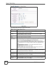
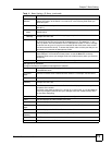
Table 10 Basic Setting > Switch Setup (continued)
LABEL DESCRIPTION