


ES-3124PWR Ethernet Switch
Hardware Connections 3-1
Chapter 3
Hardware Connections
This chapter acquaints you with the front and rear panels, shows you how to make the connections,
install/remove (optional) modules and explains the LEDs.
3.1 Front Panel
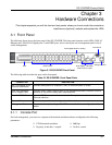
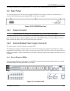
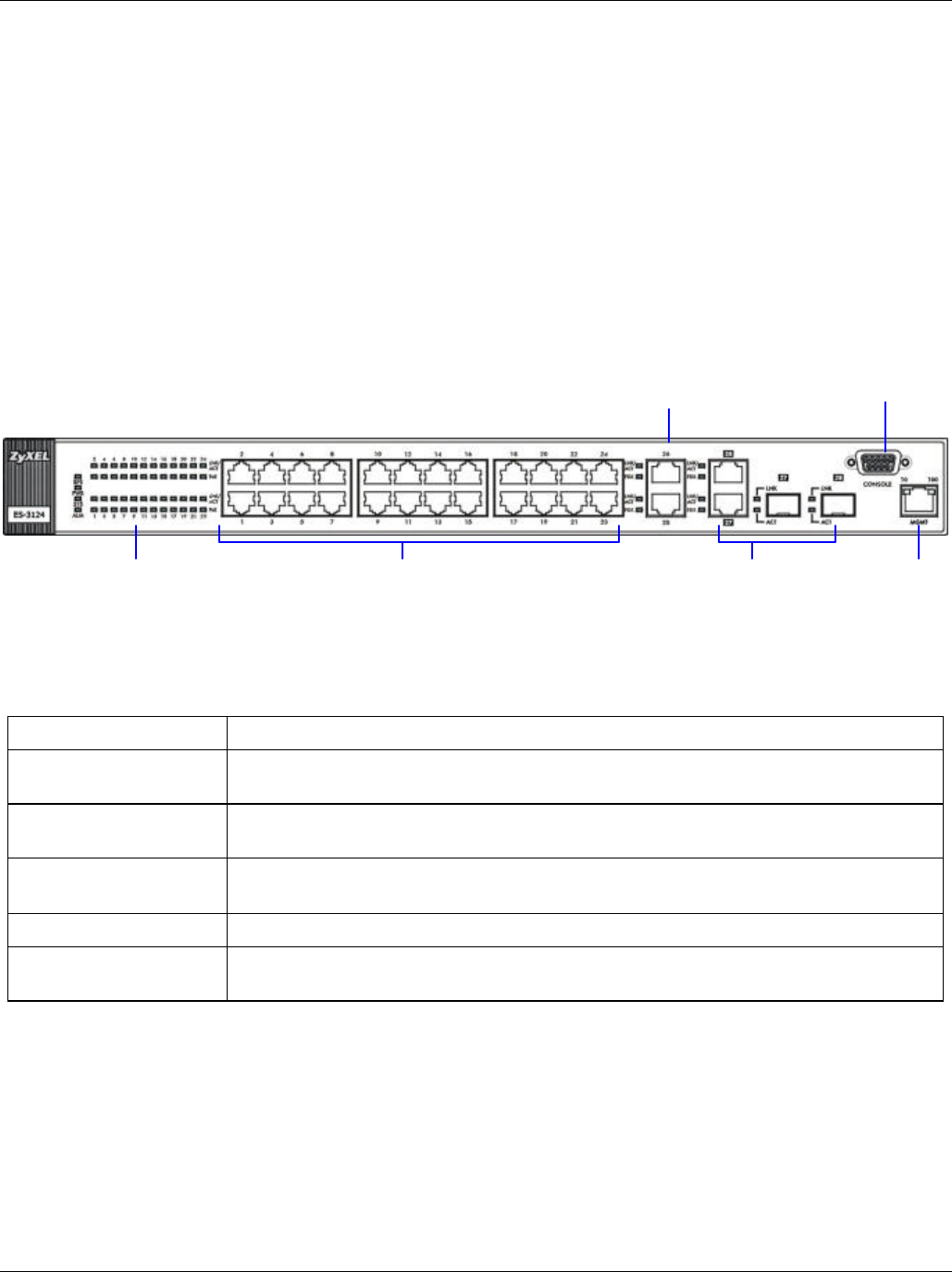
The following figure shows the front panel of the ES-3124PWR. The front panel contains switch LEDs, 24 RJ-45
Ethernet ports, four RJ-45 Gigabit ports, 2 mini-GBIC ports, and a console port and a management port for local
switch management.
Figure 3-1 ES-3124PWR Front Panel
The following table describes the ports on the front panel.
Table 3-1 ES-3124PWR: Front Panel Ports
CONNECTOR DESCRIPTION
24 10/100 Mbps RJ-45
Ethernet Connectors
Connect these ports to a computer, a hub, an Ethernet switch or router.
Four 100/1000 Mbps
RJ-45 Gigabit Ports
Connect these 1Gbps Ethernet ports to high-bandwidth backbone network Ethernet
switches or use them to daisy-chain other switches.
Two Mini-GBIC Ports Use mini-GBIC transceivers in these slots for fiber-optical connections to backbone
Ethernet switches.
Console Port The console port is for local configuration of the switch.
Management Port Connect to a computer using an RJ-45 Ethernet cable for local configuration of the
switch.
3.1.1 Console Port
For local management, you can use a computer with terminal emulation software configured to the following
parameters:
Ø VT100 terminal emulation Ø 9600 bps
Ø No parity, 8 data bits, 1 stop bit Ø No flow control
Ethernet
Ports
RJ-45 Gigabit / Mini-GBIC
Combo Ports for uplink
LEDs
Management Port
Console Port
RJ-45 Gigabit Ports for stacking