


ES-3124PWR Ethernet Switch
Hardware Connections 3-5
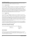
The default IP address of the management port is 192.168.0.1 with a subnet mask of 255.255.255.0
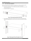
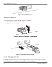
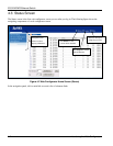
3.2 Rear Panel
The following figure shows the rear panel of the ES-3124PWR. The rear panel contains the ventilation holes, a
connector for external backup power supply (BPS) and the power receptacle.
Figure 3-6 ES-3124PWR Rear Panel
3.2.1 Power Connector
Make sure you are using the correct power source as shown on the panel.
To connect the power to the ES-3124PWR, insert the female end of power cord to the power receptacle on the rear
panel. Connect the other end of the supplied power cord to a 100~240VAC/10A power outlet. Make sure that no
objects obstruct the airflow of the fans (located on the side of the unit).
3.2.2 External Backup Power Supply Connector
The switch supports external backup power supply (BPS).
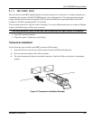
The backup power supply constantly monitors the status of the internal power supply. The backup power supply
automatically provides power to the switch in the event of a power failure. Once the switch receives power from the
backup power supply, it will not automatically switch back to using the internal power supply even when the power
is resumed.
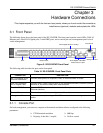
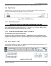
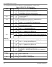
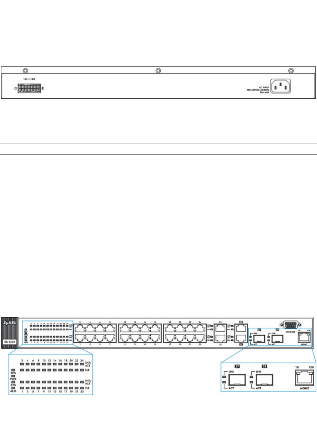
3.3 Front Panel LEDs
After you connect the power to the switch, view the LEDs to ensure proper functioning of the switch and as an aid
in troubleshooting. The front panel LEDs are as follows.
Figure 3-7 Front Panel LEDs