


Chapter 11 Trunks
ZyWALL USG 1000 User’s Guide
220
Maybe you have two connections with different bandwidths. For jitter-sensitive traffic (like
video for example), you could set up a trunk group that uses spillover or weighted round robin
load balancing to make sure that most of the jitter-sensitive traffic goes through the higher-
bandwidth interface.
For some traffic connections, you might want to use least load first load balancing in order to
even out the distribution of the traffic load.
11.4 Load Balancing Algorithms
The following sections describe the load balancing algorithms that the ZyWALL can use to
decide which interface the traffic (from the LAN) should use for a session
3
. The available
bandwidth you configure on the ZyWALL refers to the actual bandwidth provided by the ISP
and the measured bandwidth refers to the bandwidth an interface is currently using.
11.4.1 Least Load First
The least load first algorithm uses the current (or recent) outbound bandwidth utilization of
each trunk member interface as the load balancing index(es) when making decisions about to
which interface a new session is to be distributed. The outbound bandwidth utilization is
defined as the measured outbound throughput over the available outbound bandwidth.
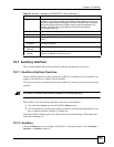
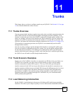
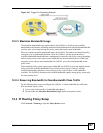
11.4.1.1 Least Load First Example 1
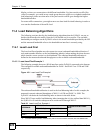
The following example shows two WAN interfaces on the ZyWALL connected to the Internet.
The configured available outbound bandwidths for WAN 1 and WAN 2 are 512K and 256K
respectively.
Figure 143 Least Load First Example 1
The outbound bandwidth utilization is used as the load balancing index. In this example, the
measured (current) outbound throughput of WAN 1 is 412K and WAN 2 is 198K. The
ZyWALL calculates the load balancing index as shown in the table below.
Since WAN 2 has a smaller load balancing index (meaning that it is less utilized than WAN 1),
the ZyWALL will send the subsequent new session traffic through WAN 2.
3. In the load balancing section, a session may refer to normal connection-oriented, UDP and SNMP2 traffic.
Table 63 Least Load First: Example 1
INTERFACE
OUTBOUND
LOAD BALANCING INDEX
(M/A)
AVAILABLE (A) MEASURED (M)
WAN 1 512 K 412 K 0.8
WAN 2 256 K 198 K 0.77