


240
EES4710BD 10 Slots L2/L3/L4 Chassis Switch
SW4(Config-Port-Range)#exit
SW4(Config)#spanning-tree
SW4(Config)#spanning-tree mst 4 priority 0
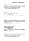
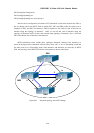
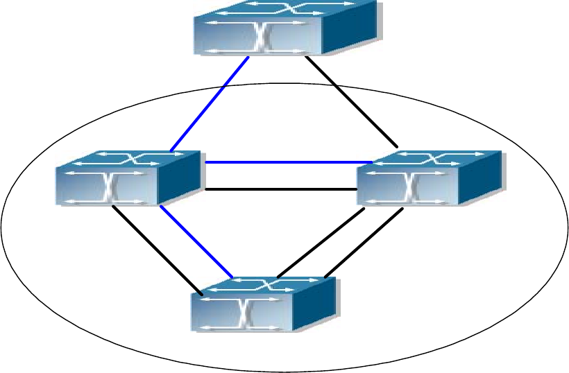
After the above configuration, all instance CIST (Instance0) of the entire network take SW1 as
the root bridge, and in the MSTP fields in which SW2, SW3 and SW4 reside, the region root of
Instance0 is SW2, and SW3 for Instance3, SW4 for Instance4. The traffic of vlan 20 and vlan 30
transmit along the topology of Instance3; traffic of vlan 40 and vlan 50 transmit along the
topology of Instance4; traffic of other vlan transmit along topology of Instance0. Port 1 of Switch
SW2 is the Master Port of Instance3 and Instance4.
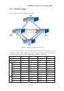
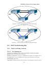
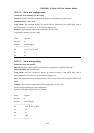
MSTP calculation results include three topologies Instance0, Instance3 and Instance4, as
shown in the figure below (indicated with blue lines). Ports with "x" are in "Discarding" mode and
the other ports are in "Forwarding" mode. Since Instance3 and Instance4 are valid only in MSTP
field, only topology in the MSTP field for the related parts are shown in the figure.
SW1
SW2
SW3
SW4
1
1
2
2
3
54
2
3
1
6
7
5
4
6
7
x
x
x
x
x
Figure 00-3 Instance0 topology after MSTP change