


Section 2 Microwave Path Engineering Basics TRACER 4106/4206 System Manual
16 © 2004 ADTRAN, Inc. 612804206L2-1A
Higher levels of fade margin indicate stronger protection against signal fading and a more reliable link. For
most applications, 20 to 30 dB of fade margin should ensure a reliable link.
The following sections further discuss the necessary power calculations and their components.
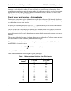
4. RECEIVER POWER
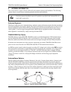
The viability of a particular microwave path is determined by the power of the transmitted microwave
signal, the transmit and receive antenna gain, distance, and accumulated system losses (such as RF coaxial
cable losses and path loss).
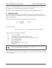
The equation relating received signal power to the other microwave parameters is
or (in decibel notation)
where the variables in the equations are defined as
P
R
received power (dBm)
P
T
transmitted power (adjustable up to 20 dBm maximum)
G
T
transmit antenna gain (decibels referenced to an isotropic source – dBi)
G
R
receive antenna gain (dBi)
λ carrier wavelength (meters)
d path distance (meters)
L other losses (RF coaxial cable, etc. – dB)
L
P
path loss (dB)
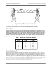
Figure 1 on page 17 illustrates a wireless link configuration containing all the parameters necessary for the
power budget analysis.
When using decibel notation, all quantities must be individually converted to decibels
prior to performing addition and subtraction.
P
R
P
T
G
T
G
R
λ
2
4
π
()
2
d
2
L
------------------------------=
(Watts, W)
(decibels referenced to a milliwatt, dBm)
P
R
= P
T
+ G
T
+ G
R
- L - L
P