


Section 3 Engineering Guidelines TRACER 4106/4206 System Manual
30 © 2004 ADTRAN, Inc. 612804206L2-1A
screen.
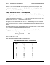
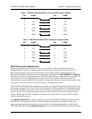
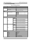
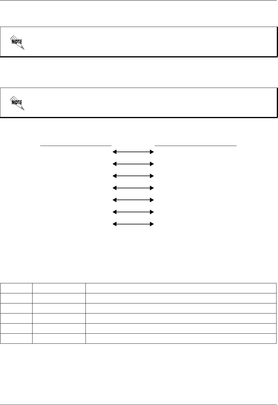
Table 5 contains the wiring diagram needed for connecting the TRACER 4106/4206 RS-232 interface to a
modem using the null modem adapter.
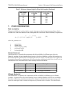
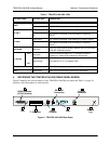
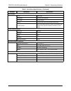
T1 Connections (RJ-48C)
The physical T1 interfaces are provided by eight RJ-48C jacks that comply with the applicable ANSI and
AT&T
®
standards.
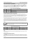
Hangup-on-DTR-drop may need to be explicitly enabled on some modems.
The null modem interface must route Carrier Detect (CD) on pin 8 directly from the
modem. When using the RS-232 interface for modem control, the modem must source CD
only when actually connected to a carrier.
Table 5. TRACER 4106/4206 (DCE) to Modem (DCE - DB-25)
PIN NAME PIN NAME
2TX 3 RX
3RX 2 TX
4RTS 5 CTS
5 CTS 4 RTS
6DSR 20 DTR
7 GND 7 GND
8CD 8 CD
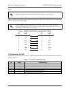
Table 6. T1 Interface Connector Pinout
PIN NAME DESCRIPTION
1
R Transmit data (ring) towards the network
2 T Transmit data (tip) towards the network
3, 6-8 UNUSED —
4 R1 Receive data (ring) toward the network
5 T1 Receive data (tip) from the network