


Section 5 User Interface Guide TRACER 4106/4206 System Manual
44 © 2004 ADTRAN, Inc. 612804206L2-1A
3. MENU DESCRIPTIONS
The remainder of this section describes the TRACER 4106/4206 menus and submenus.
>TRACER SYSTEM STATUS
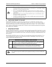
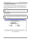
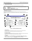
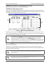
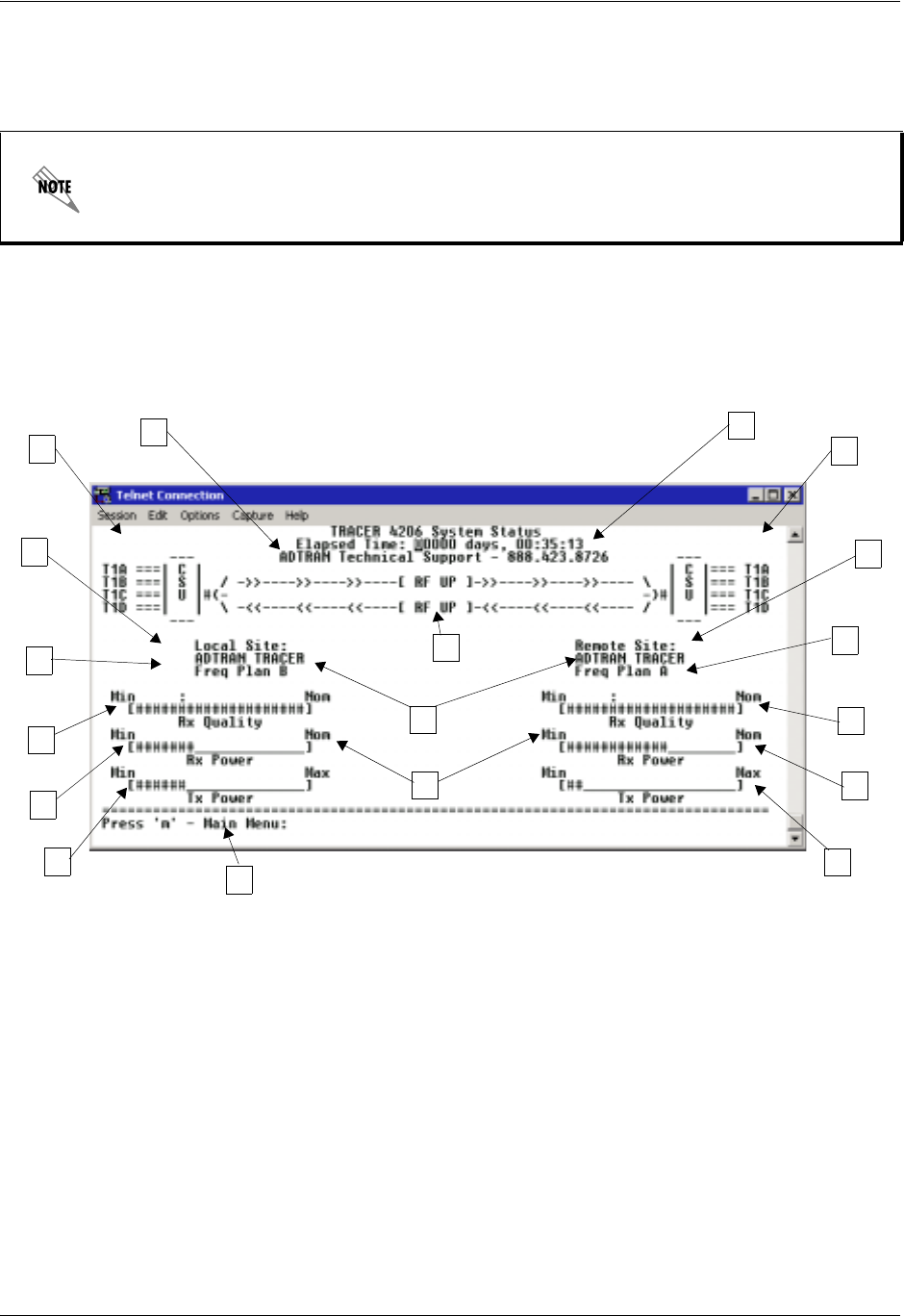
Figure 2 shows the TRACER 4106/4206 System Status menu page. The status of major system
components for both sides of the TRACER link are displayed, but no configuration can be performed from
this view.
Figure 2. TRACER 4106/4206 System Status
A. Elapsed Time
The top of the TRACER 4106/4206 System Status menu page displays the elapsed time the
TRACER 4106/4206 system has been operational since the last power reset.
B. Contact Information
The ADTRAN technical Support toll-free contact number is located directly beneath the elapsed time
display at the top of the TRACER 4106/4206 System Status menu page.
C. RF Status
A graphical indicator of the TRACER RF link is located beneath the Technical Support contact
number. The status of the received radio link is indicated as
RF UP or RF DOWN for each direction.
This RF status display corresponds to the
RF DOWN LED on the front of the unit.
The menu structure of the TRACER 4106/4206 system is depicted below as follows:
>
MENU PAGE
> MENU PAGE > MENU SELECTION
> MENU PAGE > MENU SELECTION > SUB-MENU
A
Elapsed
Time
B
Contact
Information
F
Local
H
Frequency
I
Rx Power
C
RF Status
G
D
T1 Status
E
Remote
H
I
Rx Quality
K
Tx Power
J
Tx Power
K
Navigation Reminder
(Error/Alarm
Only)
TRACER
Status
Plan
Frequency
Plan
TRACER
Status
Site Name
D
T1 Status
(Error/Alarm
Only)
L
Rx Quality
J
Rx Power
J
Rx Power