


Section 6 Troubleshooting Guide TRACER 4106/4206 System Manual
58 © 2004 ADTRAN, Inc. 612804206L2-1A
Blue Alarm
A remote alarm (alarm indication signal or AIS) is generated by the attached equipment. The root
cause must be determined at the attached equipment. A typical cause of a blue alarm is a lack of input
to a CSU.
Recommended Actions:
1. Verify the input to any attached data equipment.
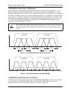
BPV
Bipolar violations (BPVs) indicate an improper configuration or faulty wiring.
Recommended Actions:
1. Verify the TRACER 4106/4206 unit and the attached equipment are configured for the same line
coding (B8ZS or AMI).
2. Verify the cable connections for the T1 interface are solid.
3. RF ERRORS
RF errors can range from a nonviable microwave path to loose RF connectors.
Nonviable path conditions could be caused by physical obstructions such as buildings, moutainous terrain,
trees, etc., as well as other physical limitations such as excessive path distances and in-band RF
interference. These types of errors are remedied by performing a detailed line-of-site microwave path
study to determine whether a microwave link is feasible for the terrain and environment under
consideration.
If after performing a microwave path study the system is still not operational, ensure that the antennas are
properly aligned. Note that alignment must be achieved in both elevation and azimuth for optimal link
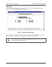
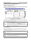
performance. The TRACER 4106/4206 can be used to aid in antenna alignment by looking at the
RX
P
OWER “fuel gauge” on the System Status or System Option menu pages or by measuring the DC voltage
(relative to ground) at the RSSI front panel test jack. Optimal antenna alignment is achieved by peaking the
front panel RSSI voltage or the the Rx Power "fuel gauge" on the TRACER 4106/4206 terminal diplay.
Consult the ADTRAN TRACER Data Sheet included with the unit to verify that the actual receive signal
level agrees with the calculated receive signal.
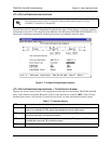
An RSSI test point, located on the front panel, provides a DC voltage level (relative to the GND test point)
that corresponds to the amount of signal being received from the far end's transmitter. The voltage at this
test point can vary from approximately 0 to 5 Volts DC. An RSSI Calibration sheet is shipped with the
system to provide the installer a cross-reference between actual received signal level (in dBm) and RSSI
voltage. This sheet is useful for verifying link budget calculations and ensuring proper equipment
installation.
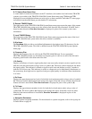
4. STEP-BY-STEP TROUBLESHOOTING
The logical troubleshooting flow presented in this section can be used to set up your TRACER 4106/4206
system, and also to diagnose a previously installed system. Please contact ADTRAN Technical support at
any stage during installation and/or troubleshooting if you require assistance.