


TRACER 4106/4206 System Manual Section 6 Troubleshooting Guide
612804206L2-1A © 2004 ADTRAN, Inc. 59
5. INSTALLING/TROUBLESHOOTING THE TRACER HARDWARE
1. Perform a detailed path profile and link budget for each TRACER 4106/4206 microwave link. A
thorough path study can be used to estimate signal power budgets, fade margins at each receiver,
identity potential line-of-site obstacles, properly size antenna dishes, and determine minimum
antenna dish heights above the earth.
2. Setup all of the TRACER hardware on a workbench. ADTRAN recommends that the actual cables
used in the permanent installation be used in the workbench setup. A rigorous workbench
“simulation” of the link will help alleviate and avoid time-consuming errors.
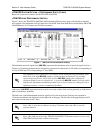
3. Examine the
PLAN A and PLAN B LEDs on the front panel of each unit. These LEDs indicate the
frequency plan for each TRACER 4106/4206 unit. The frequency plan (Plan A, Plan B) LED
should be the opposite on the TRACER 4106/4206 units.
4. Verify that both ends of the link are configured for the same RF Bandplan (1, 2, or 3). See
>TRACER System Options > RF Bandplan on page 48 for more details.
5. Verify that both ends of the link are configured for the same number of active T1 ports. See
>TRACER System Options >Active T1 Ports on page 48 for more details.
6. Attach the RF coaxial cables to be used in the permanent installation to the N-type connectors on
the back of the TRACER 4106/4206 unit. Attach the other end of the coaxial cable(s) to an RF
power meter or spectrum analyzer, if either is available. The power measured by the meter/analyzer
will be the RF power available at the input of the antenna. The TRACER 4106/4206 unit is
programmed at the factory to output approximately 100 mW (20 dBm) of RF power. The actual
power level measured by the meter/analyzer will be less than 100 mW due to RF losses through the
coaxial cable, and is a function of the cable type and length being used. In any event, the power
level at the output of the coaxial cable should be a significant fraction of 100 mW. A power
meter/analyzer reading that is not on the order of at least tens-of-milliwatts could be an indication
of any combination of either unsuitable RF, or faulty, or unreasonably long coaxial cable.
7. Resolve all RF coaxial cabling errors before proceeding.
8. Attach the RF coaxial cables to a high-quality attenuator, if possible. If you do not have an
attenuator, attach the coaxial cables to the antennas to be used in the permanent installation. If the
installation antennas are not available, small, inexpensive dipole or patch antennas can be used for
verification purposes. If an adjustable attenuator is being used, dial in the amount of attenuation
that corresponds to the path loss value expected for the microwave link in which the TRACER
hardware will be installed. The path loss value can be calculated from a knowledge of the path
length, or provided by a path study. Remember to subtract both antenna gain values from the
attenuator level if these values have not already be accounted for.
9. After setting up the RF pieces, examine the
RF DOWN LED on the front panel of each
TRACER 4106/4206 unit. If the
RF DOWN LED is illuminated (red), the corresponding
TRACER 4106/4206 is not receiving a suitable RF signal from the other TRACER 4106/4206 unit.
In this case, the receiving TRACER 4106/4206 is either receiving a very weak signal, or no signal
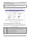
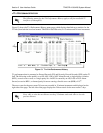
ADTRAN provides a wireless link planning tool on our website. This link budget tool is
constructed as an easy to use spreadsheet with dropdown menus so that the user can
quickly change any of the link parameters (antenna size, coaxial cable type and length,
frequency band, link distance, etc) and instantly see how the microwave path availability is
affected. This tool is available at www.adtran.com/wireless
and can be used online or
downloaded for standalone use.