


Section 5 User Interface Guide TRACER 4106/4206 System Manual
48 © 2004 ADTRAN, Inc. 612804206L2-1A
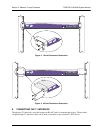
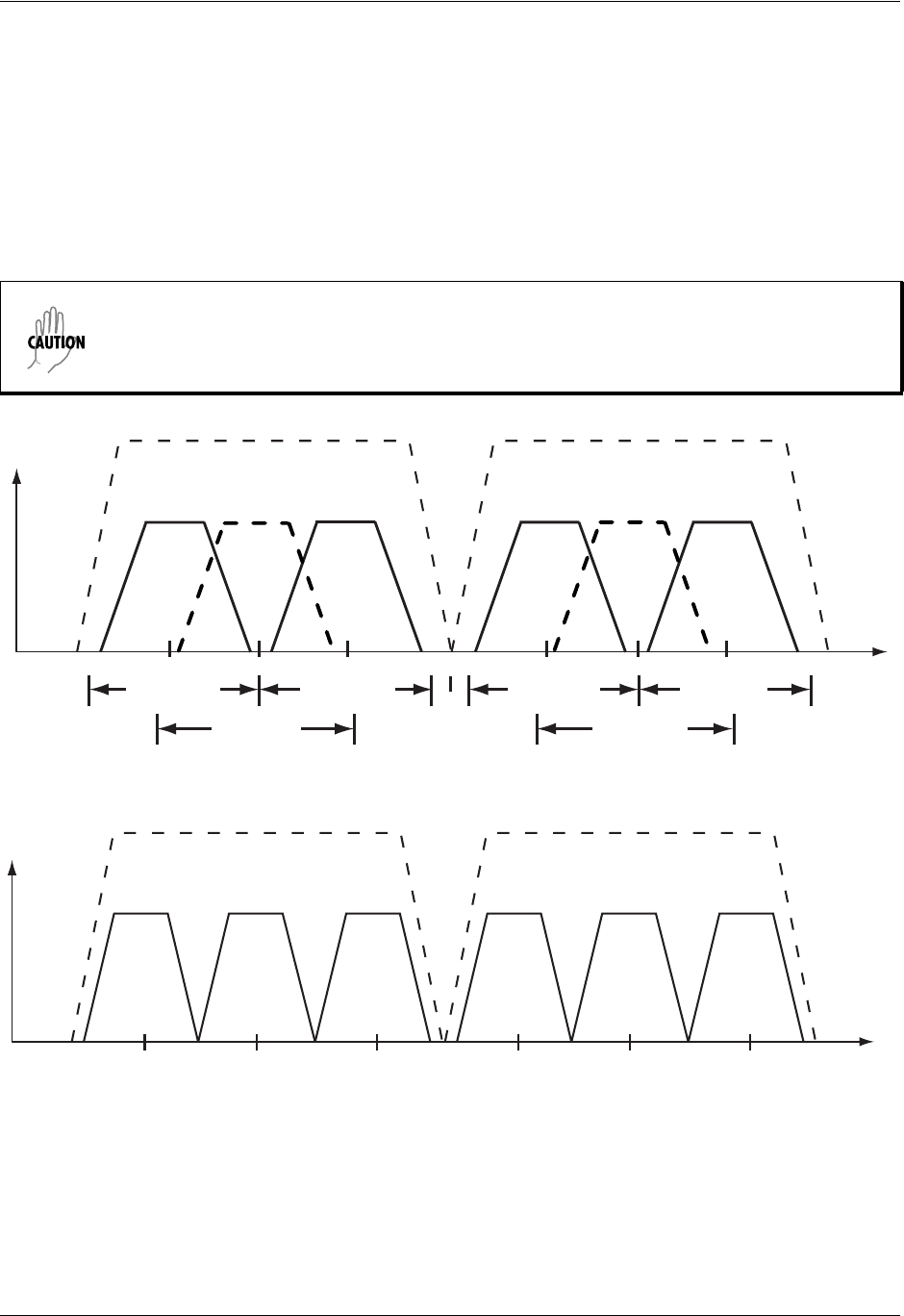
>TRACER SYSTEM OPTIONS > RF BANDPLAN
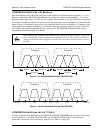
Sets the bandplan for the TRACER 4106/4206. Each channel is divided into three bandplans (1, 2, or 3).
Both local and remote TRACER 4106/4206 must be configured with the same bandplan (1, 2, or 3) but
different channel plans (Plan A or Plan B). For example, the transmitter at one end of the link will transmit
in bandplan 1 of channel A (the lower portion of the spectrum) and receive in bandplan 1 of channel B (the
upper portion). Consequently, the receiver at the other end should receive in bandplan 1 of channel A (the
lower portion) and transmit in bandplan 1 of channel B (the upper portion). (Refer to Figures 5 and 6 for
the 2.4 GHz and 5.8 GHz bandwidth division, respectively.) The TRACER 4106/4206 comes factory
programmed with RF bandplan set to Band 1.
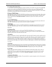
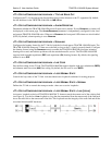
Figure 5. 2.4 GHz Bandwidth Division (TRACER 4106)
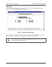
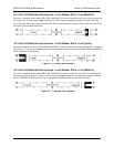
Figure 6. 5.8 GHz Bandwidth Division (TRACER 4206)
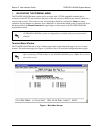
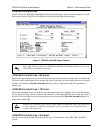
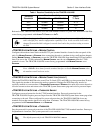
>TRACER SYSTEM OPTIONS >ACTIVE T1 PORTS
Configures the delivered bandwidth of the TRACER 4106/4206. When 4XT1 ports are active, the system
receive sensitivity is -90 dBm (TRACER 4106) and -85 dBm (TRACER 4206). As the delivered
bandwidth is decreased, receive sensitivity improves (see Table 1 on page 49).
When changing RF bandplans on installed links, change the remote end first. If the local
end is changed first, remote configuration capability is lost. In the event the local end is
changed first and the link is dropped, reset the local end to the previous setting to restore
the link.
Channel!A
2416 2441.752422 24282400 MHz 2483.5!MHz
Bandplan!3
Bandplan!2
Bandplan!1
Channel!B
2456 2462 2468
Bandplan!3
Bandplan!2
Bandplan!1
Channel!A
57345725 5787 58505744 5753MHz MHz
Bandplan!3Bandplan!2Bandplan!1
Channel!B
5814 5824 5833
Bandplan!3Bandplan!2Bandplan!1