


Section 4 Network Turnup Procedure TRACER 4106/4206 System Manual
38 © 2004 ADTRAN, Inc. 612804206L2-1A
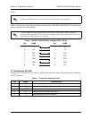
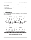
To designate the utilization of the ISM bandwidth, there are two different channel plans, labeled A and B.
The letter of each channel plan setting is preset by the factory and refers to the physical configuration of
the diplexer filter inside the chassis. Each channel is then divided into three bandplans (1, 2 or 3). The
bandplans must be the same for the local and remote TRACER 4106/4206. For example, the transmitter at
one end of the link will transmit in bandplan 1 of channel A (the lower portion of the spectrum) and receive
in bandplan 1 of channel B (the upper portion). Consequently, the receiver at the other end should receive
in bandplan 1 of channel A (the lower portion) and transmit in bandplan 1 of channel B (the upper portion).
The letter of the channel plan (A or B) must be different on both ends and the number of the bandplan (1, 2,
or 3) must be the same on both ends. The default bandplan configuration for the TRACER 4106/4206 is
bandplan 1.
The channel plan (A or B) of the unit may be changed in the field, if necessary, by rewiring the internal
diplexer. Contact ADTRAN Technical Support for more information on this procedure.
5. GROUNDING INSTRUCTIONS
The following provides grounding instruction information from the Underwriters’ Laboratory UL 60950
Standard for Safety of Information Technology Equipment Including Electrical Business Equipment, of
December 2000.
An equipment grounding conductor that is not smaller in size than the ungrounded branch-circuit supply
conductors is to be installed as part of the circuit that supplies the product or system. Bare, covered, or
insulated grounding conductors are acceptable. Individually covered or insulated equipment grounding
conductors shall have a continuous outer finish that is either green, or green with one or more yellow
stripes. The equipment grounding conductor is to be connected to ground at the service equipment.
The attachment-plug receptacles in the vicinity of the product or system are all to be of a grounding type,
and the equipment grounding conductors serving these receptacles are to be connected to earth ground at
the service equipment.
A supplementary equipment grounding conductor shall be installed between the product or system and
ground that is in addition to the equipment grounding conductor in the power supply cord.
The supplementary equipment grounding conductor shall not be smaller in size than the ungrounded
branch-circuit supply conductors. The supplementary equipment grounding conductor shall be connected
to the product at the terminal provided, and shall be connected to ground in a manner that will retain the
ground connection when the product is unplugged from the receptacle. The connection to ground of the
supplementary equipment grounding conductor shall be in compliance with the rules for terminating
bonding jumpers at Part K or Article 250 of the National Electrical Code, ANSI/NFPA 70. Termination of
the supplementary equipment grounding conductor is permitted to be made to building steel, to a metal
electrical raceway system, or to any grounded item that is permanently and reliably connected to the
electrical service equipment ground.
The supplemental grounding conductor shall be connected to the equipment using a number 8 ring terminal
and should be fastened to the grounding lug provided on the rear panel of the equipment. The ring terminal
should be installed using the appropriate crimping tool (AMP P/N 59250 T-EAD Crimping Tool or
equivalent.)
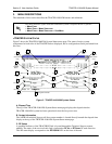
The supplemental equipment grounding terminal is located on the rear panel of the
TRACER 4106/4206.