


Section 2 Microwave Path Engineering Basics TRACER 4106/4206 System Manual
22 © 2004 ADTRAN, Inc. 612804206L2-1A
Antennas are also designed to radiate RF energy efficiently for a specific range of frequencies. Please
consult the data sheet for your particular antenna make and model to ensure that it is specified to operate in
the 2400 MHz to 2483.5 MHz frequency band for TRACER 4106 models, and the 5725 MHz to 5850
MHz frequency band for the TRACER 4206 system.
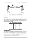
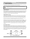
Fresnel Zones, Earth Curvature, & Antenna Heights
Fresnel zones correspond to regions in the microwave path where reflections of the intended signal occur
and combine in both constructive and destructive manners with the main signal, thereby either enhancing
or reducing the net power at the receiver.
In general, the odd numbered Fresnel zones (1, 3, 5, ...) add constructively at the receiver, while the even
numbered Fresnel zones (2, 4, 6, ...) add destructively at the receiver.
The first Fresnel zone corresponds to the main lobe, 60% of which must be free of physical obstructions
for the path calculations to be valid. Since the main lobe contains the vast majority of the microwave
energy, this zone is typically used to determine proper antenna heights when placing antennas on towers or
buildings.
The curvature of the Earth becomes a legitimate obstruction for path lengths of 7 miles or greater, and must
also be accounted for when determining minimum antenna heights.
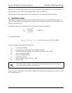
The aggregate expression for minimum antenna height that incorporates both the 60% first Fresnel zone
and the Earth’s curvature is given by
where f is in GHz and d is in miles.
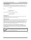
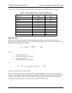
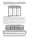
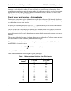
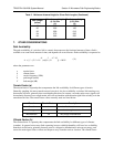
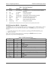
Table 5 tabulates minimum antenna heights for given path lengths.
Table 5. Minimum Antenna Height for Given Path Lengths
Path Length
(miles)
Min. Antenna Height
@ 2.4 GHz
(ft)
Min. Antenna Height
@ 5.8 GHz
(ft)
233 22
448 32
661 41
873 50
10 85 60
14 111 81
16 124 92
18 138 104
20 153 117
22 169 131
24 185 145
26 202 161
h72.1
d
4f
-----
0.125d
2
+=
(feet)