


TRACER 4106/4206 System Manual Section 3 Engineering Guidelines
612804206L2-1A © 2004 ADTRAN, Inc. 27
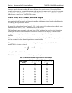
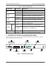
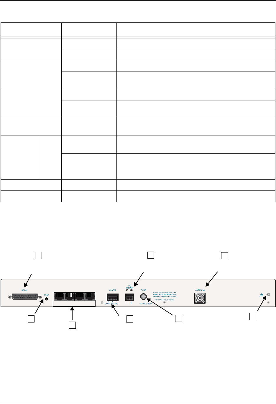
4. REVIEWING THE TRACER 4106/4206 REAR PANEL DESIGN
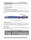
Figure 2 identifies the various features of the TRACER 4106/4206 rear panel and Table 1 on page 26
provides a brief description of each interface.
Figure 2. TRACER 4106/4206 Rear Panel
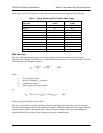
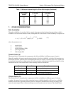
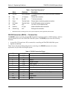
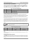
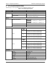
Table 2. TRACER 4106/4206 LEDs
For these LEDs... This color light... Indicates that...
PWR
Green (solid) the TRACER 4106/4206 is connected to a power source.
Off the TRACER 4106/4206 is not currently powered up.
PLAN A
Green (solid) the TRACER 4106/4206 is transmitting on Frequency Plan A.
Off
the TRACER 4106/4206 is not transmitting on Frequency
Plan A.
PLAN B
Green (solid) the TRACER 4106/4206 is transmitting on Frequency Plan B.
Off
the TRACER 4106/4206 is not transmitting on Frequency
Plan B.
RF DOWN Red (solid)
there is a communication problem between the local and remote
TRACER 4106/4206 systems.
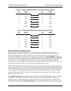
T1 Alarms
T1A
.
.
.
.
T1D
Red (solid)
there is an Alarm Condition on a T1 Interface. Check the
respective T1 status page to identify the active alarm.
Red (blinking) the respective T1 is in a loopback mode.
RF LOW Red (solid) the RSSI level is approaching 0 Volts of RSSI.
TST Amber (solid) there is an active test being performed by the system.
T1A T1B T1C T1D
A
Antenna
DC Power
Connection
Connector
T1 Interfaces
RS232 Interface
(VT100 Terminal)
Ground
Lug
Fuse
Alarm
Contacts
Test
E
G
B
C
D
F
H