


Section 3 Engineering Guidelines TRACER 4106/4206 System Manual
28 © 2004 ADTRAN, Inc. 612804206L2-1A
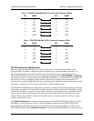
RS-232 Connection (DB-25) — Terminal Use
The RS-232 connector provides a female DB-25 terminal connection (wired as a DCE interface), which is
used for terminal access to the TRACER 4106/4206 system. The
RS-232 port provides the following
functions:
• Accepts EIA-232 input from a PC or terminal for controlling the TRACER 4106/4206 system
• Operates at 9600 bps
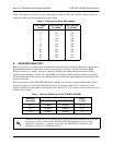
Table 2 shows the pinout. Wiring diagrams for connecting to the RS-232 connector (for various
applications) are provided following the pinout.
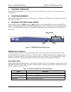
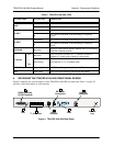
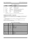
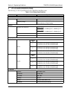
Table 1. Rear Panel Description
1
1 Detailed discussions (including pinouts) of rear panel components (where applicable) follow the table.
Name Connector Description
A RS-232 DB-25 (female) VT100 terminal (or PC with terminal emulation software)
connection
B Test 1/4” bantam Factory test connection
C T1A - T1D RJ-48C T1 device connection
D Alarm Terminal block External alarm monitoring system connection
E DC Power Terminal block 21-60 VDC power source connection
F Fuse N/A 2 A, 250 V, 2 inch slow-blo fuse
G Antenna N-Type Antenna feedline cable connection
H Ground Lug N/A Earth ground connection
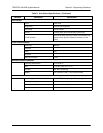
Table 2. RS-232 Connection Pinout
PIN NAME DESCRIPTION
1, 7
GND Ground
2 TX Transmit
3 RX Receive
4 RTS Request To Send
5 CTS Clear To Send
6 DSR Data Set Ready (Modem Control Only)
8 CD Carrier Detect
9-19 — Unused
20 DTR Data Terminal Ready (Modem Control Only)
21 — Unused
22 RI Ring Indicator
23-25 — Unused