Multicast Boundary Specifications Configuring Multicast Address Boundaries
page 5-2 OmniSwitch 6800/6850/9000 Advanced Routing Configuration Guide December 2007
Multicast Boundary Specifications
Note. If software routing is used, the number of total flows supported is variable, depending on the
number of flows and the number of routes per flow.
Quick Steps for Configuring Multicast Address
Boundaries
Using Existing IP Interfaces
1 Before attempting to configure a multicast address boundary, be sure that you have manually loaded
the multicast protocol software for your network (e.g., PIM-SM or DVMRP). Otherwise, you will receive
an error stating that “the specified application is not loaded.” To manually load multicast protocol soft-
ware, use the ip load command. For example:
-> ip load pim
2 Configure a multicast address boundary for a VLAN interface using the ip mroute-boundary
command. Information must include the interface IP address, followed by the multicast boundary address
and the corresponding subnet mask. For example:
-> ip mroute-boundary vlan-3 239.120.0.0 255.255.0.0
On New IP Interface
1 Be sure that you have loaded one of the dynamic routing features (e.g., PIM-SM). Otherwise, you will
receive an error stating that “the specified application is not loaded.” To load a dynamic routing feature,
use the ip load command. For example:
-> ip load pim
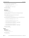
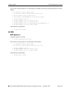
2 Create a new IP interface on an existing VLAN by specifying a valid IP address. For example:
-> ip interface vlan-2 address 178.14.1.43 vlan 3
Note. The ip interface command is not supported in Release 5.3.1. For this release use the vlan router ip
command instead. See the OmniSwitch CLI Reference Guide for more information.
The VLAN must already be created on the switch. For information about creating VLANs, see the
“Configuring VLANs” chapter in the OmniSwitch 6800/6850/9000 Network Configuration Guide.
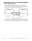
RFCs Supported 2365—Administratively Scoped IP Multicast
2932—IPv4 Multicast Routing MIB
Maximum Multicast Flows per Network
Interface (NI) Module
400 (with hardware routing; see note below)
Valid Scoped Address Range 239.0.0.0 to 239.255.255.255


