


OSPFv3 Overview Configuring OSPFv3
page 2-10 OmniSwitch 6800/6850/9000 Advanced Routing Configuration Guide December 2007
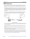
Classification of Routers
When an AS is split into OSPFv3 areas, the routers are further divided according to function into the
following four overlapping categories:
• Internal area router. A router with all directly connected networks belonging to the same area. Each
internal router shares the same LSDB with other routers within the same area.
• Area border router (ABR). A router that attaches to multiple areas and to the backbone area. ABRs
maintain a separate LSDB for each area to which it is connected, in addition to an AS and link-local
database. The topological information from each area LSDB is condensed by the ABR and flooded to
other areas.
• Designated router (DR). An elected router that is responsible for generating LSAs and maintaining
the LSDB for the subnet to which the router is connected. The DR updates the LSDB by exchanging
database updates with adjacent, non-designated routers on the network.
• AS boundary router. A router that exchanges routing information with routers belonging to other
Autonomous Systems. Such a router may also advertise external routes throughout the Autonomous
System. The path to each AS boundary router is known by every router in the AS. This classification is
completely independent of the previous classifications (i.e., internal and area border routers). AS
boundary routers may be internal or area border routers.
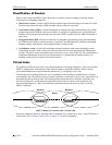
Virtual Links
It is possible to define areas in such a way that the backbone is no longer contiguous. (This is not an ideal
OSPFv3 configuration, and maximum effort should be made to avoid this situation.) In this case the
system administrator must restore backbone connectivity by configuring virtual links.
Virtual links can be configured between any two backbone routers that have a connection to a common
non-backbone area. The protocol treats two routers joined by a virtual link as if they were connected by an
unnumbered point-to-point network. The routing protocol traffic that flows along the virtual link uses
intra-area routing only, and the physical connection between the two routers is not managed by the
network administrator (i.e., there is no dedicated connection between the routers as there is with the
OSPFv3 backbone).
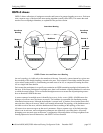
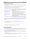
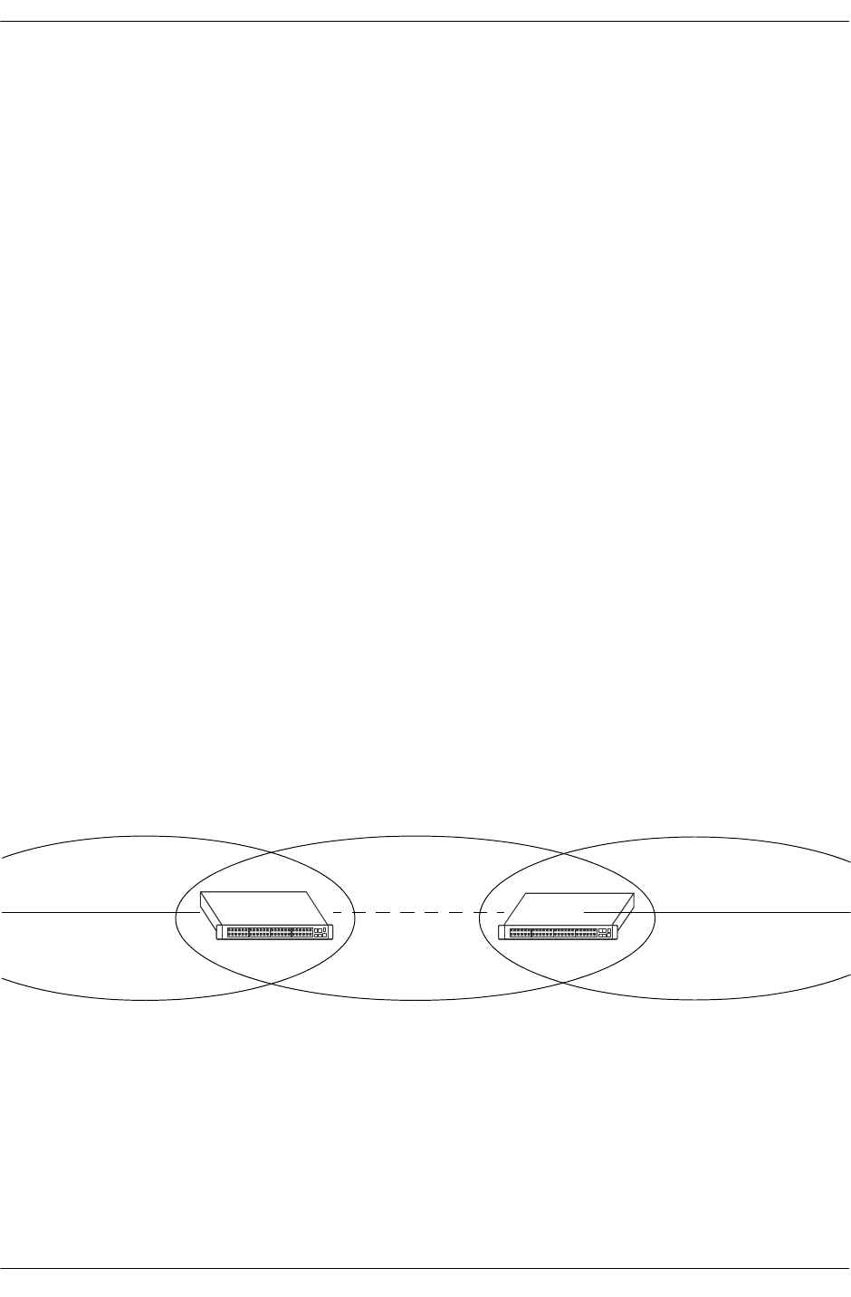
OSPFv3 Routers Connected with a Virtual Link
In the above diagram, Router A and Router B are connected via a virtual link in Area 1, which is known as
a transit area. See “Creating Virtual Links” on page 2-17 for more information.
Router A
Router B
Backbone
Virtual Link
Area 1
Backbone