


Configuring OSPF OSPF Overview
OmniSwitch 6800/6850/9000 Advanced Routing Configuration Guide December 2007 page 1-9
Classification of Routers
When an AS is split into OSPF areas, the routers are further divided according to function into the follow-
ing four overlapping categories:
• Internal routers. A router with all directly connected networks belonging to the same area. These
routers run a single copy of the SPF algorithm.
• Area border routers. A router that attaches to multiple areas. Area border routers run multiple copies
of the SPF algorithm, one copy for each attached area. Area border routers condense the topological
information of their attached areas for flooding to other areas.
• Backbone routers. A router that has an interface to the backbone. This includes all routers that inter-
face to more than one area (i.e., area border routers). However, backbone routers do not have to be area
border routers. Routers with all interfaces connected to the backbone are considered to be internal rout-
ers.
• AS boundary routers. A router that exchanges routing information with routers belonging to other
Autonomous Systems. Such a router has AS external routes that are advertised throughout the Autono-
mous System. The path to each AS boundary router is known by every router in the AS. This classifi-
cation is completely independent of the previous classifications (i.e., internal, area border, and
backbone routers). AS boundary routers may be internal or area border routers, and may or may not
participate in the backbone.
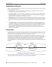
Virtual Links
It is possible to define areas in such a way that the backbone is no longer contiguous. (This is not an ideal
OSPF configuration, and maximum effort should be made to avoid this situation.) In this case the system
administrator must restore backbone connectivity by configuring virtual links.
Virtual links can be configured between any two backbone routers that have a connection to a common
non-backbone area. The protocol treats two routers joined by a virtual link as if they were connected by an
unnumbered point-to-point network. The routing protocol traffic that flows along the virtual link uses
intra-area routing only, and the physical connection between the two routers is not managed by the
network administrator (i.e., there is no dedicated connection between the routers as there is with the OSPF
backbone).
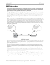
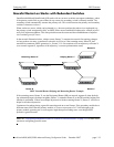
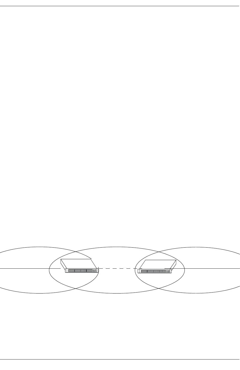
OSPF Routers Connected with a Virtual Link
In the above diagram, Router A and Router B are connected via a virtual link in Area 1, which is known as
a transit area. See “Creating Virtual Links” on page 1-22 for more information.
Router A
Router B
Backbone
Virtual Link
Area 1
Backbone