


Configuring Multicast Address Boundaries Application Example for Configuring Multicast Address Boundaries
OmniSwitch 6800/6850/9000 Advanced Routing Configuration Guide December 2007 page 5-9
4 You are now ready to create a boundary on the core switch’s router interface. For this example, the
broadest possible boundary, 239.0.0.0, will be configured on the interface. This boundary will keep all
traffic addressed to multicast addresses 239.0.0.0 through 239.255.255.255 from being forwarded on the
interface. To assign the boundary, use the ip mroute-boundary command. For example:
-> ip mroute-boundary vlan-2 239.0.0.0 255.0.0.0
Note that the command includes the interface IP address (178.10.1.1), along with the multicast address
boundary (239.0.0.0) and the corresponding subnet mask (255.0.0.0).
5 Verify your changes using the show ip mroute-boundary command:
-> show ip mroute-boundary
Interface Name Interface Address Boundary Address
--------------+-----------------+-------------------
vlan-2 178.10.1.1 239.0.0.0/8
The correct multicast address boundary of 239.0.0.0 is shown on VLAN 2. (VLAN 2 is displayed in the
table because it contains the IP interface on which the boundary was configured. In this case, that IP inter-
face is 178.10.1.1.) In addition, the subnet mask has been translated into the CIDR prefix length of /8.
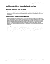
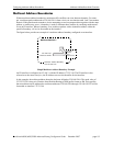
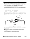
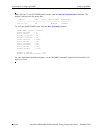
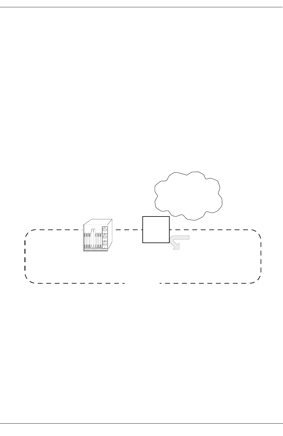
The figure below illustrates the multicast address boundary as currently configured.
Network with a Single Multicast Address Boundary
All multicast traffic ranging from 239.0.0.0 through 239.255.255.255 is blocked and cannot be forwarded
from switch’s 178.10.1.1 router interface. As shown by the arrow, multicast traffic addressed to 239.x.x.x
cannot leave the domain.
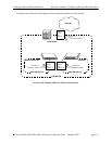
6 Next, create a VLAN on the wiring closet switch used for Human Resources. For example:
-> vlan 3
VLAN 3 is now used to define the Human Resources network domain.
VLAN 2
Router
Port
178.10.1.1
Internet
Core Switch
239.x.x.x
Multicast Traffic
239.0.0.0/8