


Chapter 1: Overview
28
described in Table 3. .
A port connected to a network node that is not a powered device (that is, a
device that receives its power from another power source) functions as a
regular Ethernet port, without PoE. The PoE feature remains enabled on
the port but no power is delivered to the device.
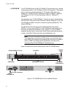
Implementation A standard Ethernet twisted pair cable contains four pairs of strands for a
total of eight strands. 10/100 Mbps network traffic requires only four
strands (1, 2, 3, and 6), leaving four strands in the cable unused (4, 5, 7,
and 8).
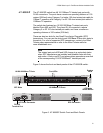
The PoE standard, IEEE 802.3af, describes two alternative ways for
delivering power to a powered device (PD) over twisted pair cabling.
Alternative A uses the same strands that carry the network traffic.
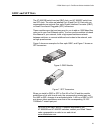
Alternative B uses the spare strands. The PoE implementation on the AT-
8524POE Layer 2+ Fast Ethernet Switch is Alternative A, where power is
transmitted over strands 1, 2, 3, and 6.
PD’s that comply with the IEEE 802.3af standard typically support both
power delivery methods. So long as a PD is compliant with the standard, it
should be able to receive its power from the switch while using either a
straight or cross-over cable. The PoE feature on the AT-8524POE Layer
2+ Fast Ethernet Switch should also work with most legacy PD’s as long
as the device can be powered on pins 1, 2, 3, and 6. A legacy device is a
node that was manufactured before the IEEE 802.3af standard was
completed and, consequently, may not adhere to the standard. If this is
the case, a straight (MDI) cable may be needed to insure that the DC
polarity is correct.
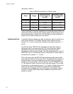
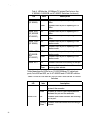
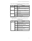
Table 3. IEEE 802.3af Class vs. Power Levels
Class Usage
Minimum Power
Levels Output at
the PSE
Maximum Power
Levels Output at
the PD
0 Default 15.4W 0.44W to 12.95W
1 Optional 4.0W 0.44W to 3.84W
2 Optional 7.0W 3.84W to 6.49W
3 Optional 15.4W 6.49W to 12.95W