AT-8500 Series Layer 2+ Fast Ethernet Switches Installation Guide
31
LEDs
This section provides information on the LEDs found on the AT-8500
Series switches:
“Twisted Pair Port LEDs and the LED Mode Select Button,” next
“Fiber Optic Port LEDs” on page 34
“GBIC and SFP Expansion Slot LEDs” on page 35
“System LEDs” on page 36
Twisted Pair Port
LEDs and the
LED Mode Select
Button
This section applies to the AT-8524M, AT-8524POE, AT-8550GB, and
AT-8550SP switches.
The port LEDs on the front panel display port status information. Each port
has two LEDs. One of the LEDs displays the status of the link between a
port and its end node. The second LED, labeled MODE, displays a variety
of status information, depending on the switch model. You use the Mode
Select button on the front panel to toggle the Mode LEDs to display
different status information. The LEDs next to the Mode Select button
indicate the status being displayed by the port Mode LEDs.
Note
Toggling the Mode Selection button does not affect the normal
operations of the switch.
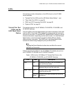
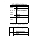
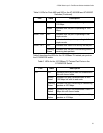
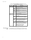
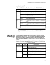
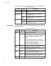
Table 4 describes the LEDs for the 10/100Base-TX twisted pair ports on
the AT-8524M, AT-8550GB, and AT-8550SP switches.
Table 4. LEDs for the 10/100Base-TX Twisted Pair Ports on the
AT-8524M, AT-8550GB, and AT-8550SP Switches
LED State Description
LINK OFF Indicates that there is no link between the
port and the end node.
Green Indicates a valid link has been established
between the port and the end node.
Mode - COL OFF Indicates that no data collisions are
occurring on the port.
Flashing
Green
Indicates that data collisions are occurring
on the port.


