


Chapter 3: Troubleshooting
78
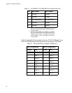
Verify that you are using the appropriate category of twisted pair cable:
Category 3 or better for 10 Mbps operation and Category 5 and
Category 5E for 100 Mbps and 1000 Mbps operations.
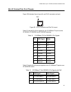
Determine if a crossover cable is required. Since the twisted pair ports
feature auto MDI/MDI-X, you should be able to use a straight-through
cable regardless of the type of device you connect to a port. However,
if you disable Auto-Negotiation on a port and set a port’s speed and
duplex mode manually, the port defaults to MDI-X. For port pinouts,
refer to “RJ-45 Twisted Pair Port Pinouts” on page 83.
Make sure that the operating parameters of the port on the switch are
compatible with the end node to which the port is connected. This may
require that you use the switch’s management software. For
instructions, refer to the AT-S62 Management Software User’s Guides.
Fiber Optic Port Link LED is Off
For fiber optic ports, verify that the LINK LED for each port is ON. If a LINK
LED is OFF, do the following:
Verify that the end node connected to the port is powered ON and is
operating properly.
Check that the fiber optic cable is securely connected to the port on
the switch and to the port on the end node.
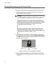
Dual SC ports consist of two separate connectors, as shown in Figure
32 on page 90. Each connects to a separate fiber strand. One is for
receiving data and the other is for transmitting data. When connecting
a fiber optic cable to an SC port, be sure that the receiver fiber
connector is connected to the transmitter connector on the remote end
node, and the transmitter fiber connector is connected to the receiver
connector on the remote node.
Make sure that you are using the appropriate type of fiber optic cable
and that the cable length does not exceed the allowed maximum
distance. For an AT-8516F Series switch, refer to “Planning the
Installation” on page 52 . For an optional GBIC or SPF module, or
other expansion module, refer to the Installation Guide shipped with
the module.
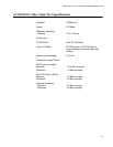
Use a fiber optic tester to test the attenuation on the cable to
determine if the strength of the fiber optic signal falls below acceptable
limits. (For fiber optic port specifications for an AT-8516F Series
Switch, refer to “AT-8516F/SC Fiber Optic Port Specifications” on
page 85. For an optional GBIC or SPF module, or other expansion
module, refer to the Installation Guide shipped with the module.
Check that the operating specifications (for instance, wavelength and
maximum operating distance) of the fiber optic port on the remote end
node are compatible with the fiber optic port on the switch. For