


Appendix A: Technical Specifications
88
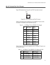
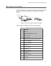
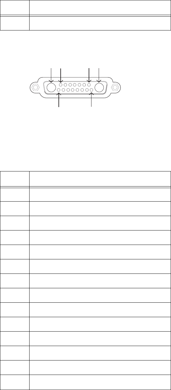
Figure 31 illustrates the pin layout to the RPS connector on the
AT-8524POE switch.
Figure 31. AT-8524POE RPS Connector Pin Layout
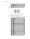
Table 17 lists the RPS connector pins and definitions.
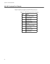
16 +3.3V DC Return
Table 16. Pin Definitions of the 16-pin RPS Connector (Continued)
Pin Definition
A1A2 17
15 8
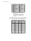
Table 17. Pin Definitions for the RPS Connector on the AT-8524POE
Switch
Pin Definition
A1 48V Return
A2 Return
1 48V
2 48V RS+
3 Redundant Power Supply (RPS) present
4 12V RS-
5 12V RS+
6 12V
73.3V
8 48V
9 48V
10 48V RS-
11 RPS GOOD
12 3.3V RS-