9
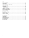
Table 1. Safety Symbols .....................................................................................................................................................12
Table 2. Model Configurations ............................................................................................................................................16
Table 3. IEEE 802.3af Class vs. Power Levels ..................................................................................................................28
Table 4. LEDs for the 10/100Base-TX Twisted Pair Ports on the AT-8524M, AT-8550GB, and AT-8550SP Switches .....31
Table 5. LEDs for Ports 49R and 50R on the AT-8550GB and AT-8550SP Switches .......................................................32
Table 6. LEDs for the 10/100Base-TX Twisted Pair Ports on the AT-8524POE Switch .....................................................33
Table 7. LEDs for the Fiber Optic Ports on the AT-8516F/SC Switch ................................................................................35
Table 8. LEDs for the Optional GBIC and SFP Ports on an AT-8550GB and AT-8550SP Switches .................................35
Table 9. System LEDs ........................................................................................................................................................36
Table 10. Twisted Pair Cabling and Distances ...................................................................................................................52
Table 11. Fiber Optic Cabling and Distances .....................................................................................................................53
Table 12. 10/100Base-TX Port MDI/MDI-X Pin Signals ....................................................................................................83
Table 13. 10/100Base-T Port MDI/MDI-X Pin Signals with PoE .........................................................................................83
Table 14. MDI and MDI-X Pin Signals (1000Base-T) .........................................................................................................84
Table 15. RS-232 Terminal Port Pin Signals ......................................................................................................................86
Table 16. Pin Definitions of the 16-pin RPS Connector ......................................................................................................87
Table 17. Pin Definitions for the RPS Connector on the AT-8524POE Switch ...................................................................88
Tables


