


AT-8500 Series Layer 2+ Fast Ethernet Switches Installation Guide
69
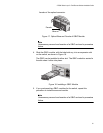
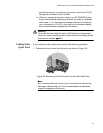
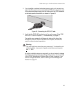
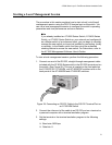
4. If you installed an optional redundant power supply unit, connect one
end of the DC power cord included with the RPS unit to the back panel
of the redundant power supply and the other end to the RPS connector
on the back panel of the switch, as shown in Figure 24.
Figure 24. Connecting the RPS DC Cable
5. Verify that the PWR LED on the front of the unit is green. If the PWR
LED is OFF, refer to Chapter 3, “Troubleshooting” on page 77.
The switch runs a series of self-diagnostic tests, which take a few
seconds to perform. After the self tests are complete, the switch is
ready for normal network operations.
Warning
This unit might have more than one power cord. To reduce the risk
of electric shock, disconnect all power cords before servicing the
unit. E30
No further installation steps are required if you do not intend to change
the default operating parameter settings of the switch, which are listed
in the AT-S62 Management Software User’s Guide. However, if you
want to manage the switch, refer to “Starting a Local Management
Session” on page 73.