


Chapter 2: Installation
56
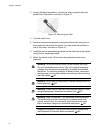
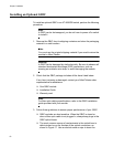
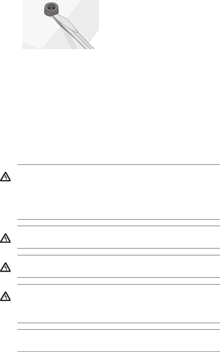
2. Using a flat-head screwdriver, remove the snap-on plastic feet from
the bottom of the switch, as shown in Figure 13.
Figure 13. Removing the Feet
3. Turn the switch over.
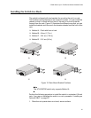
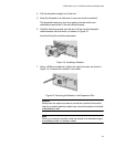
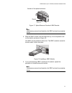
4. Attach a rackmounting bracket to one side of the switch using four of
the screws that came with the switch. You can install the brackets in
one of four ways, as shown in Figure 12.
5. Install the second rackmounting bracket on the other side of the switch
using the four remaining screws.
6. Mount the switch in the 19-inch rack using standard screws (not
provided).
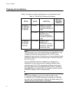
Warning: To prevent electric shock, do not remove the cover.
No user-serviceable parts inside. This unit contains hazardous
voltages and should only be opened by a trained and qualified
technician. To avoid the possibility of electric shock, disconnect
electric power to the product before connecting or disconnecting
the LAN cables.
E1
Warning: Do not work on equipment or cables during periods of
lightning activity.
E2
Warning: Power cord is used as a disconnection device. To de-
energize equipment, disconnect the power cord.
E3
Warning: Class I Equipment. This equipment must be earthed.
The power plug must be connected to a properly wired earth
ground socket outlet. An improperly wired socket outlet could
place hazardous voltages on accessible metal parts.
E4
Pluggable Equipment. The socket outlet shall be installed near
the equipment and shall be easily accessible.
E5