


Chapter 2: Installation
70
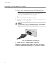
Wiring and Powering on an DC Powered Unit
To provide power for a DC powered switch, perform the following steps:
1. Before you attach wires to the DC terminal block at the rear of the
switch, review the following warning:
Warning
As a safety precaution, install a circuit breaker with a minimum value
of 15 Amps between the equipment and the DC power source.
Always connect the wires to the LAN equipment first before you
connect the wires to the circuit breaker. Do not work with HOT feeds
to avoid the danger of physical injury from electrical shock. Always
be sure that the circuit breaker is in the OFF position before
connecting the wires to the breaker. E9
A tray cable is required to connect the power source if the unit is
powered by centralized DC power. The tray cable must be a UL
listed Type TC tray cable and rated at 600 V and 90 degrees C, with
three conductors, minimum 14 AWG. E24
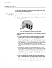
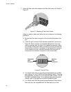
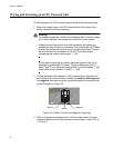
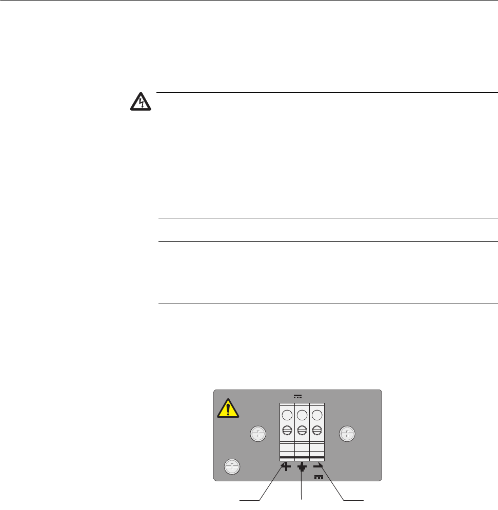
2. On the rear side of the chassis is a DC terminal block. Starting from
the left side of the terminal block, identify the positive, frame ground,
and negative terminals using the symbols beneath the terminal block
or the illustration in Figure 25.
Figure 25. Positive, Ground, and Negative Terminals
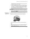
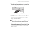
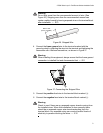
3. With a 14-gauge wire-stripping tool, strip the three wires in the tray
cable coming from the DC input power source to 8mm ± 1mm (0.31 in.,
± 0.039 in.).
FOR CENTRALIZED DC
POWER CONNECTION,
INSTALL ONLY IN A
RESTRICTED AREA
DC INPUT
36-60VDC
Positive
Ground
Negative