


Chapter 2: Installation
66
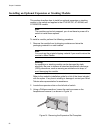
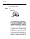
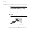
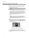
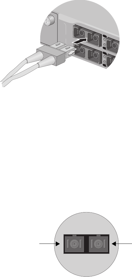
2. Attach the fiber optic data cables to the fiber optic ports, as shown in
Figure 21.
Figure 21. Attaching a Fiber Optic Cable
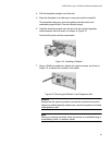
When you attach a fiber optic cable, be sure to observe the following
guidelines:
Be sure that the cable connector is firmly locked into place in the
port.
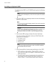
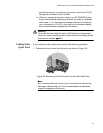
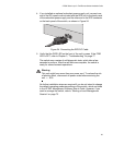
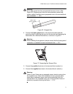
A dual SC port consists of two separate connectors, as shown in
Figure 22. Each connects to a separate fiber strand. One is for
receiving packets and the other is for transmitting packets. When
you connect a fiber optic cable to a dual SC port, be sure that the
receiver fiber connector is connected to the transmitter connector
on the remote end node, and the transmitter fiber connector is
connected to the receiver connector on the remote node.
Figure 22. Dual SC Port
You should verify that you are using the appropriate type of fiber
optic cabling. For an AT-8516F/xx Series switch, refer to “Planning
the Installation” on page 52. For an optional GBIC module, refer to
the GBIC installation guide. For an optional fiber optic expansion
module, refer to the expansion module installation guide.
You should verify that the operating specifications of the switch’s
fiber optic port are compatible with the fiber optic port on the
18
D/C
L/A
D
/
C
L
/A
TX
TX
1
TX RX
9
TX
RX
1TX RX
SC Port
Transmitter
Fiber
Connector
Receiver
Fiber
Connector