


AT-8500 Series Layer 2+ Fast Ethernet Switches Installation Guide
55
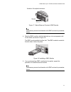
Installing the Switch in a Rack
The switch is shipped with two brackets for mounting the unit in a rack.
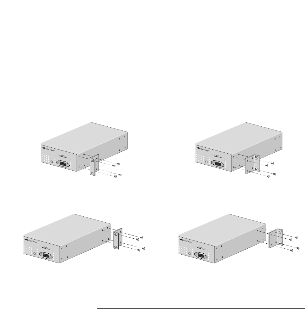
The brackets can be attached to the chassis four ways. You can install the
chassis so that it is flush with the front of the rack or so that it extends
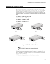
forward from the rack. Figure 12 illustrates the different ways that you can
install the brackets and how much the chassis extends from the front of the
rack.
Method A - Flush with front of rack
Method B - 4.5cm (1.75 in.)
Method C - 18.4 cm (7.25 in.)
Method D - 21.6 cm (8.5 in)
Figure 12. Rack Mount Bracket Positions
Note
The AT-8524POE switch only supports Method A.
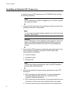
Perform the following procedure to install the switch in a standard 19-inch
rack. If you are not installing the switch in a rack, proceed to “Installing an
Optional GBIC” on page 60.
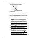
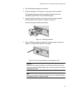
1. Place the unit upside down on a level, secure surface.
17
19 21 23
18
20 22 24
COL
100
FULL
ACT
FAULT
RPS
MASTER
PWR
M
ODE
STATUS
AT-8524M
Fast E
thernet Sw
itch
17
19 21 23
18
20 22 24
COL
100
FULL
ACT
FAULT
RPS
MASTER
PW
R
MO
DE
STATUS
AT-8524M
Fast Ethernet Switch
17 19 21 23
18
20 22 24
COL
100
FULL
ACT
FAULT
RPS
MASTER
PWR
M
ODE
STATUS
AT-8524M
Fast Ethernet Switch
17
19 21 23
18 20 22 24
COL
100
FULL
ACT
FAULT
RPS
MASTER
PWR
M
ODE
STATUS
AT-8524M
Fast Ethernet Sw
itch
AB
CD