Chapter 1: Overview
38
Power Options and Connectors
This section provides information about the power options and features on
the AT-8500 Series switches:
“RPS Connector,” next
“AC Power Connector” on page 39
“DC Power Connector” on page 39
RPS Connector The RPS connector on the back panel of the switch connects to an
optional AT-RPS3004 or AT-RPS3104 redundant power supply unit.
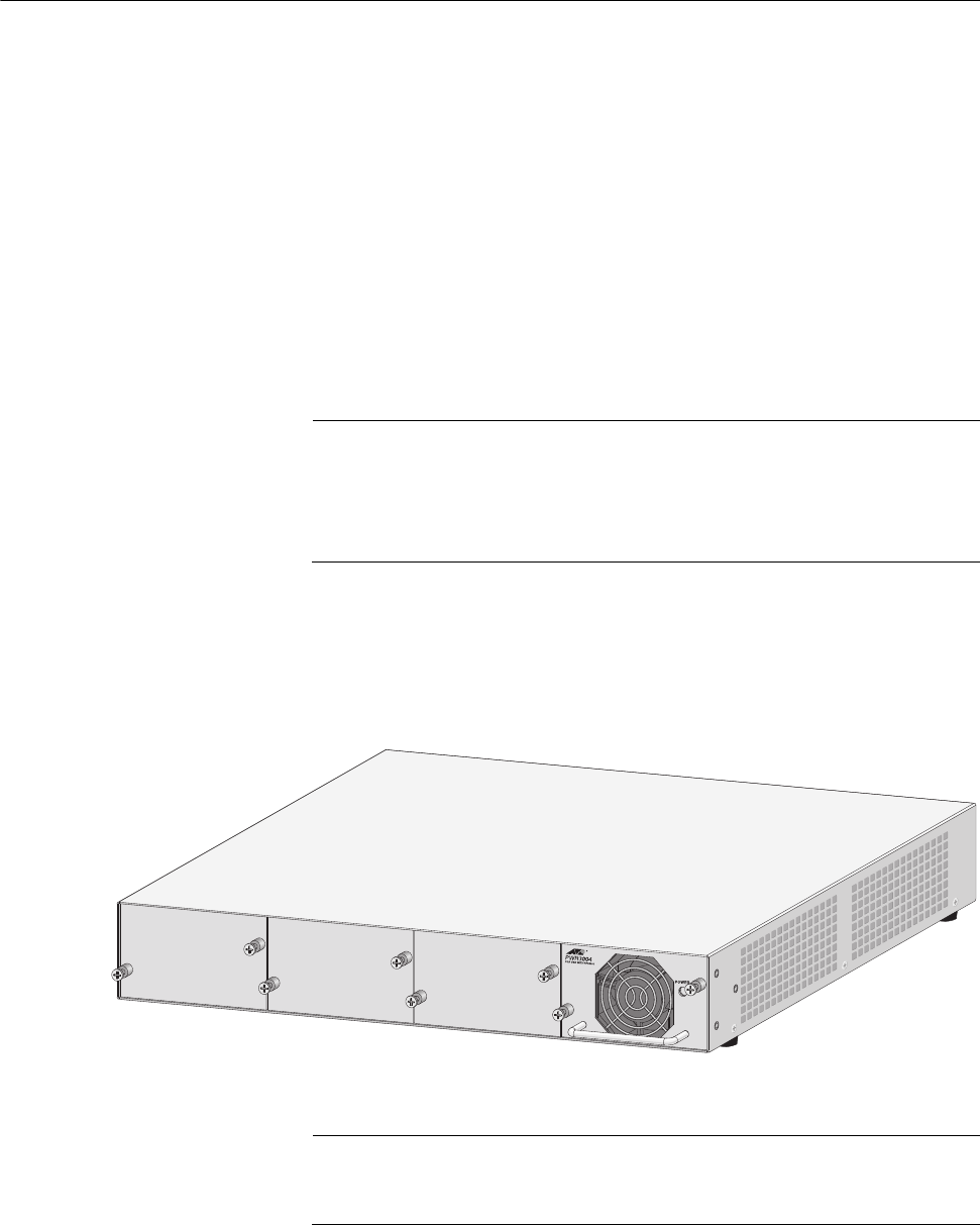
Figure 8 illustrates an AT-RPS3004 unit. A redundant power supply unit
can provide power to the switch in the event the switch’s internal power
supply should fail.
Note
The AT-RPS3004 unit is used with the AT-8516F/SC, AT-8524M,
AT-8550GB, and AT-8550SP switches. The AT-RPS3104 unit is
used with the AT-8524POE switch. Do not use the AT-RPS3004 unit
with the AT-8524POE switch.
A redundant external power supply comes with one pre-installed power
module and has three empty slots for additional power modules. Each
power module can support one switch, making the unit capable of
supporting up to four switches simultaneously.
Figure 8. AT-RPS3004 Redundant Power Supply Unit
Note
DC models of the AT-8500 Series switches do not feature an RPS
connector.


