


AT-8500 Series Layer 2+ Fast Ethernet Switches Installation Guide
83
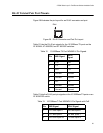
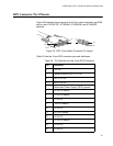
RJ-45 Twisted Pair Port Pinouts
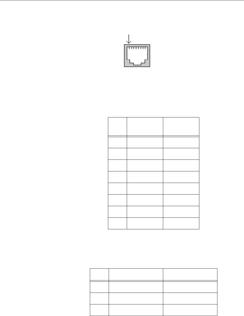
Figure 29 illustrates the pin layout for an RJ-45 connector and port.
Figure 29. RJ-45 Connector and Port Pin Layout
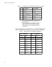
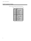
Table 12 lists the RJ-45 pin signals for the 10/100Base-TX ports on the
AT-8524M, AT-8550GB, and AT-8550SP switches.
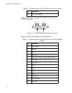
Table 13 lists the RJ-45 port pin signals on the 10/100Base-TX ports on an
AT-8524POE switch.
Pin 1
Table 12. 10/100Base-TX Port MDI/MDI-X Pin Signals
Pin MDI Signal
MDI-X
Signal
1TX+ RX+
2TX- RX-
3RX+ TX+
4 Unused Unused
5 Unused Unused
6RX- TX-
7 Unused Unused
8 Unused Unused
Table 13. 10/100Base-T Port MDI/MDI-X Pin Signals with PoE
Pin MDI Signal MDI-X Signal
1 TX+ and Vport-1
1
RX+ and Vport-1
2 TX- and Vport-1 RX- and Vport-1
3 RX+ and Vport-2
2
TX+ and Vport-2