


AT-8500 Series Layer 2+ Fast Ethernet Switches Installation Guide
61
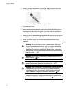
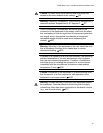
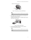
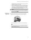
ferrules of the optical connector.
Figure 17. Optical Bore and Ferrule of GBIC Module
Note
Unnecessary removal and insertion of a GBIC can lead to premature
failure.
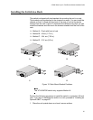
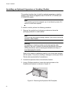
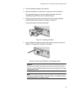
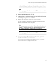
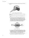
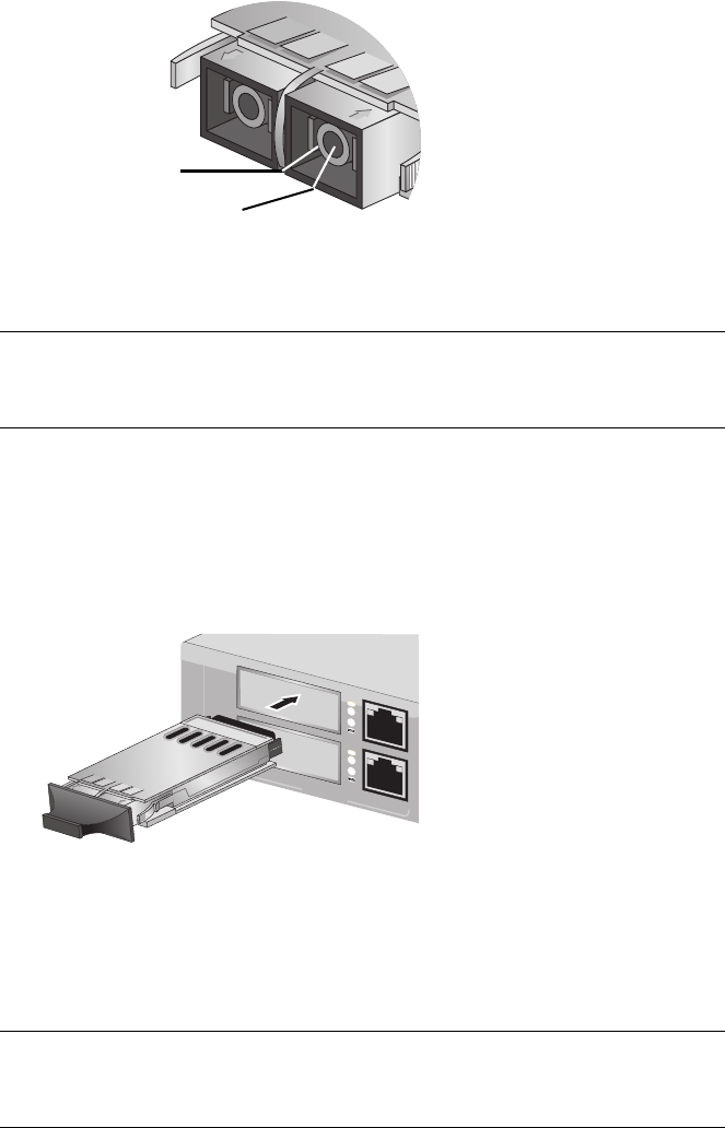
4. Slide the GBIC module, with the label side up, into an expansion slot
on the switch, as shown in Figure 18.
The GBIC can be installed in either slot. The GBIC module is seated in
the slot when it clicks into place.
Figure 18. Installing a GBIC Module
5. If you purchased two GBIC modules for the switch, repeat this
procedure to install the second module.
Note
Unnecessary removal and insertion of a GBIC can lead to premature
failure.
Ferrule
Bore
LINK
LINK
MODE LINK49R
MODE LINK50R
10/100/1000BASE-T
49
50
1
000
BAS
E-X
UPLINK P
OR
TS