


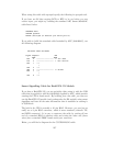
When using this cable with apcupsd specify the following in apcupsd.conf:
If you have an OS that requires DCD or RTS to be set before you can
receive input, you might try building the standard APC Smart 940-0024C
cable listed below.
UPSCABLE smart
UPSTYPE apcsmart
DEVICE /dev/ttyS0 (or whatever your serial port is)
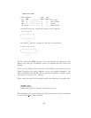
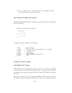
If you wish to build the standard cable furnished by APC (940-0024C), use
the following diagram.
APC Smart Cable 940-0024C
Signal Computer UPS
DB9F DB9M
RxD 2 -------------------- 2 TxD Send
TxD 3 -------------------- 1 RxD Receive
DCD 1 --*
|
DTR 4 --*
GND 5 -------------------- 9 Ground
RTS 7 --*
|
CTS 8 --*
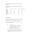
Smart Signalling Cable for BackUPS CS Models
If you have a BackUPS CS, you are probably either using it with the USB
cable that is supplied or with the 940-0128A supplied by APC, which permits
running the UPS in dumb mode. By building your own cable, you can now
run the BackUPS CS models (and perhaps also the ES models) using smart
signalling and have all the same information that is available as running it
in USB mode.
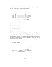
The jack in the UPS is actually a 10 pin RJ45. However, you can just as
easily use a 8 pin RJ45 connector, which is more standard (ethernet TX,
and ISDN connector). It is easy to construct the cable by cutting off one
end of a standard RJ45-8 ethernet cable and wiring the other end (three
wires) into a standard DB9F female serial port connector.
Below, you will find a diagram for the CUSTOM-RJ45 cable:
137